The way it was is shown in the attached zoom-in. Notice missing connection from pin 1 to the output copper pour in the red circle. The feedback components R2, C10, R4 are connected as they should.
The EN pin is properly connected to VIN (upper left pin in the attached zoom-in) but I measure only -150mV on the output after I connected the output pin to the output copper pour.
You may want to check the voltage at the feedback pin. That way you may get an indication if the reg is broke or if there is another issue, like with resistor values.
C2, and possibly C12, seem unsoldered at one side.
Jan
I'll check the feedback pin in current setup. I remember it measured around -250mV before I fixed the output pin connection.
I'll check the feedback pin in current setup. I remember it measured around -250mV before I fixed the output pin connection.
Should be -1.18 when operating correctly.
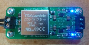
After changing the TPS7A3001 the PSU finally works! The rails measure +12.20VDC and -12.12VDC (less than 0.7% difference from each other and around 1.7% above the target). All within Vref tolerances of the regs.
The tests/measurements under load I'll probably do on the weekend.
Regards,
Oleg
The tests/measurements under load I'll probably do on the weekend.
Regards,
Oleg
Attachments
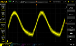
Just measured the input and output of the PSU. Under load pulling roughly 100mA from each rail, the input shows 50mVpp 83kHz ripple without indication of spike noise. The output is clean so the scope does even trigger. Interestingly, my earlier measurements all showed around 200kHz input ripple under heavier load and now it is 83kHz. Puzzling isn't it? Also the waveform has changed.
Attachments
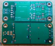
Just received new batch of PCBs with corrected error and some minor modifications/improvements. From now on all my line level projects will run off DC-DC converters. Getting away from directly dealing with mains power makes the life of a diyer so much simpler.
Regards,
Oleg
Regards,
Oleg
Attachments
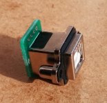
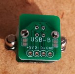
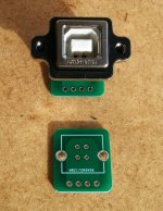
For power inlet I found a nice USB-B socket (mouser part number 523-MUSB-D511-N0). To make it easier to use I also made a small backplane PCB for it (see attached).
Attachments
Hi Oleg,
I know 2 years passed, but how does it work? Happy with these? Do you have gerbers/BOM to share?
Thank you
I know 2 years passed, but how does it work? Happy with these? Do you have gerbers/BOM to share?
Thank you
Hi Sergi,
I am happy with the PSU which is in daily use in my audio system. I use similar design to power my OPA1622 based head-amp with great success. The only downside is relatively low output current due to regs which I use. It is enough for most line-level duties by people tend to want more 🙂 I am thinking of making higher power version of this PSU but have not started with it yet. The BOM is in my vendors thread. As for sharing the gerbers I am not sure yet. The board layout is simple enough to be copied if someone is really interested and I have no problem with that. But I do not want to see my boards sold in hundreds on various shopping platforms made one-to-one using my gerbers...
Regards,
Oleg
Hi Oleg
Thank you so much
Great! I was aiming at 5V@3A for the RPi supply, but can do with lower for the other inputs. There are DC-DC ready for that I-V, and I was already done for using better capable LDO (or even not so ultra low noise regulators if they provide more current).I am happy with the PSU which is in daily use in my audio system.
(...)
The only downside is relatively low output current due to regs which I use. It is enough for most line-level duties by people tend to want more 🙂 I am thinking of making higher power version of this PSU but have not started with it yet.
Hey that's a very nice side project! I will eventually need one of those probably (will be the last part I tackle, need to do the inputs first)I use similar design to power my OPA1622 based head-amp with great success.
Pretty cool, that will be very helpful.The BOM is in my vendors thread.
Hey, fair enough man. There's lots of info in this thread in order to get going.As for sharing the gerbers I am not sure yet. The board layout is simple enough to be copied if someone is really interested and I have no problem with that. But I do not want to see my boards sold in hundreds on various shopping platforms made one-to-one using my gerbers...
Regards,
Oleg
Thank you so much
Hi again Oleg,
Is the input common mode choke also responsible for that max current output, or just the output regulators? I'm trying to understand the choke use and limitations.
Thank you
The only downside is relatively low output current due to regs which I use. It is enough for most line-level duties by people tend to want more 🙂
Is the input common mode choke also responsible for that max current output, or just the output regulators? I'm trying to understand the choke use and limitations.
Thank you
The CM choke is chosen to withstand enough current to supply the regs. It is easy to find a bigger choke if the PSU would require it. So it is not a limiting factor. The regs are...
Regards,
Oleg
Regards,
Oleg
Cool, thank you. Still unsure of the CM choke use. If only to reduce ripple, wouldn't it be enough to follow DC-DC datasheet? Normally they advise for some specific low-ESR caps to reduce input/output ripple. If at all, they advise CL as an EMC filter. But I haven't seen CM choke being mentioned in any datasheet for any use. Just curious.The CM choke is chosen to withstand enough current to supply the regs. It is easy to find a bigger choke if the PSU would require it. So it is not a limiting factor. The regs are...
Regards,
Oleg
Hi Oleg,
Thank you for that article, very detailed.
One of the main reasons (at least for me) to use an Isolated DC-DC converter is to avoid sharing grounds. I might be mistaken, but my understanding is that in this situation the choke would not not needed.
Maybe I'm missing something though…?
Thank you for that article, very detailed.
One of the main reasons (at least for me) to use an Isolated DC-DC converter is to avoid sharing grounds. I might be mistaken, but my understanding is that in this situation the choke would not not needed.
Maybe I'm missing something though…?
- Home
- Amplifiers
- Power Supplies
- DC-DC converter based PSU for line level applications