The situation is exactly the opposite. If there is no direct connecting between the input and output grounds of the DC-DC converter the CM currents will look for other paths possible and will find it through the interconnects and safety ground connection of other attached equipment. Thus by avoiding the direct ground loop and corresponding noise we create a CM noise issue which needs to be dealt with.
Thank you again. I need some time to digest all this. For instance, quoting your previous article (emphasis mine):
Also, just spotted C14 between -Vi (input ground) and COM (output ground) in your schematics (post 42). Sorry for the very stupid question, but does this create a return path for ground and/or break the isolation?
To add more mess to my brain, I found some Recom and Murata application notes about it:
Very low noise filter for isolated DC/DC converters
Recom - Powerline DC-DC Application Notes
Power line noise countermeasures using common mode choke coils
As I said, I need some (long) time to digest all this 🙂
Thank you so much again
With no external current path from input to output, (i.e. the
converter is driving isolated resistors that have very little
capacitance back to the input) the common mode current is
contained in the converter and flows through the stray
capacitance from the input to the output, causing no further
problems.
Also, just spotted C14 between -Vi (input ground) and COM (output ground) in your schematics (post 42). Sorry for the very stupid question, but does this create a return path for ground and/or break the isolation?
To add more mess to my brain, I found some Recom and Murata application notes about it:
Very low noise filter for isolated DC/DC converters
Recom - Powerline DC-DC Application Notes
Power line noise countermeasures using common mode choke coils
As I said, I need some (long) time to digest all this 🙂
Thank you so much again
The quoted statement is describing a totally isolated load. In reality you have your equipment connected together by interconnects which effectively complete an alternative CM current path from the converter's output to it's input ground as I wrote above.
C14 effectively shorts the CM loop at very high frequencies preventing upstream and downstream power network HF noise pollution. From what I know most higher power DC-DC converters have this capacitor built-in by default to meet the EMC norms.
C14 effectively shorts the CM loop at very high frequencies preventing upstream and downstream power network HF noise pollution. From what I know most higher power DC-DC converters have this capacitor built-in by default to meet the EMC norms.
Hi and thank you again for your answers (and patience 😱)
 Are those caps between input/output breaking the isolation? If so, and if those are "compulsory", how can they sell it as an Isolated DC-DC?
And yes, you're right, it's recommended in application notes (i.e. the "Recom - Powerline DC-DC Application Notes" linked above has a section on Common Mode Chokes for EMC). I just don't get it. Unless using caps across in/out does not break isolation, that is.
Been also reading the DC-DC Book of Knowledge. Practical tips for the User PDF from Steve Roberts, M.Sc. B.Sc. Technical Director, RECOM). Veeeery interesting book.
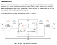
Surprisingly, in section 5.3.2 Common Mode Output Filtering he says
I'm still trying to digest all this amount of info, please bear with me. And thank you for hand-holding in the process.
Fair enoughThe quoted statement is describing a totally isolated load. In reality you have your equipment connected together by interconnects which effectively complete an alternative CM current path from the converter's output to it's input ground as I wrote above.
Noted, still makes me goC14 effectively shorts the CM loop at very high frequencies preventing upstream and downstream power network HF noise pollution. From what I know most higher power DC-DC converters have this capacitor built-in by default to meet the EMC norms.
Are those caps between input/output breaking the isolation? If so, and if those are "compulsory", how can they sell it as an Isolated DC-DC? And yes, you're right, it's recommended in application notes (i.e. the "Recom - Powerline DC-DC Application Notes" linked above has a section on Common Mode Chokes for EMC). I just don't get it. Unless using caps across in/out does not break isolation, that is.
Been also reading the DC-DC Book of Knowledge. Practical tips for the User PDF from Steve Roberts, M.Sc. B.Sc. Technical Director, RECOM). Veeeery interesting book.
Surprisingly, in section 5.3.2 Common Mode Output Filtering he says
As if there was a real option to not use the caps. On section 5.3.3 Common Mode Chokes he also saysThere are two ways to reduce common mode interference; “short-circuiting” the noise via a low impedance path or using common mode chokes.
In some applications, it is not desirable to have common mode capacitors across the isolation barrier. For example, medical equipment has strict leakage current restrictions that could be exceeded by having a low impedance path across the isolation barrier for high frequencies. In such applications, a common mode choke must be used.
(…)
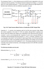
Common mode chokes will attenuate CM noise over a wide range of frequencies due to the high permeability of the core material. This is important to filter out both the main switching frequency and its harmonics.
I'm still trying to digest all this amount of info, please bear with me. And thank you for hand-holding in the process.
The last two quotes are spot on on what is going on. On my boards I use both CM choke to have broad band CM filtering and caps to short the CM loop at HF. The HF bridge across the isolation barrier in audio equipment does not add problems since it acts at frequencies not relevant for audio. In other equipment, where true isolation is needed for safety reasons such capacitors may be an issue as mentioned in the last quote. If you are concerned about the effect of those capacitors across the isolation barrier just skip them and use the CM choke only.
Last edited:
Primary to secondary capacitance for these purposes, meeting common mode noise requirements, in mains applications is permissible if the capacitors are suitably rated Class Y devices and ground leakage currents are kept below the required levels. They can also tame stability problems where feedback across the isolation boundary is used generally with high speed opto-couplers. Sometimes you will see one Y device in parallel with an R[Y]C series network to damp transient ringing.
I'm still at the stage of trying to understand things, but i will probably follow your schematics 100%. One extra doubt is, in that DC-DC Book linked above, Recom CTO includes a choke in the input and one in the output (since all the pins are affected), see capture.The last two quotes are spot on on what is going on. On my boards I use both CM choke to have broad band CM filtering and caps to short the CM loop at HF. The HF bridge across the isolation barrier in audio equipment does not add problems since it acts at frequencies not relevant for audio. In other equipment, where true isolation is needed for safety reasons such capacitors may be an issue as mentioned in the last quote. If you are concerned about the effect of those capacitors across the isolation barrier just skip them and use the CM choke only.
Primary to secondary capacitance for these purposes, meeting common mode noise requirements, in mains applications is permissible if the capacitors are suitably rated Class Y devices and ground leakage currents are kept below the required levels. They can also tame stability problems where feedback across the isolation boundary is used generally with high speed opto-couplers. Sometimes you will see one Y device in parallel with an R[Y]C series network to damp transient ringing.
Noted, thank you
Attachments
The output CM choke will be difficult to incorporate due to bi-polar output of the DC-DC converter which ideally would require a three winding choke.
The output CM choke will be difficult to incorporate due to bi-polar output of the DC-DC converter which ideally would require a three winding choke.
You're absolutely right, again 🙂
Bi-polar output chokes are also treated in that book, see captures below
Attachments

I wrote Steve Roberts from Recom, he's been sooooo nice answering my doubts as well. Everyone is so nice, guys, thank you! Basically I was freaking out about the caps possibly breaking the isolation. Answer: they don't.
Also asked him about 3 winding chokes:
No. What is important is that the dielectric strength of the capacitor can withstand permanent mains voltage across it – so the capacitor must be class Y. For some standards (household, medical), two Y-capacitors in series must be used across an isolation boundary. This is in case one capacitor fails short circuit, then the second still provides isolation. For other applications (industry, IT) only one Y-capacitor is required (the failure rate is close to zero).
Also asked him about 3 winding chokes:
Würth Elektronik WE-SL3 series (e.g. DigiKey 732-14096-2-ND), TDK ACM2520 (e.g. DigiKey 445-4842-2-ND) or Murata NGF series (e.g. Digikey 490-18604-2-ND) are all freely available. The need for an output filter is dependent on the application – you may get away just with an input filter and output capacitors.
Great! I've got away with the input filter and output capacitors 😉 I just added ferrite beads to the converter outs to get rid of the switching noise spikes.
Great! I've got away with the input filter and output capacitors 😉 I just added ferrite beads to the converter outs to get rid of the switching noise spikes.
Yeah, I'm starting to understand more, now. He also answered:
Nothing that you guys hadn't told me, but I needed to digest, or read in other words, maybe. Thank you againBoth are usually needed. An interference filter operates like a frequency-dependent voltage divider. You could make an interference filter using a resistor and capacitor as a low pass filter: at higher interference frequencies, the capacitor’s impedance will decrease, but the resistor stays the same, so the output will be divided down. If the resistor is replaced with an inductor, then with increasing frequency, the impedance of the inductor increases and the impedance of the capacitor decreases, so the dividing down is multiplied and the attenuation is stronger.
If I write a long post I write it in an external editor and copy/paste it in the reply field ... I do it after I lost several long posts in the past 🙂
If I write a long post I write it in an external editor and copy/paste it in the reply field ... I do it after I lost several long posts in the past 🙂
yeah, me too! but i was an idiot and pressed the preview instead of post... then closed the draft and the browser tab! 😱
fortunately i could recover the text from reopening the chrome tab and resending the form
- Home
- Amplifiers
- Power Supplies
- DC-DC converter based PSU for line level applications