Complete SE Amp FB Pair Output
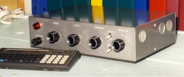
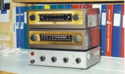
I built this little amplifier back in 1968. Since then it has been used in quite a wide variety of locations. For the past few years it has been in my workshop. Program sourc*es are an Eico HFT-90 FM receiver and a matching Eico HFT-94 AM receiver. And sometimes a CD player.
The electronics is a FB pair consisting of a 6AU6 & 6AQ5 driving into a Hammond 125D OPT. The front end is a 12AX7 connected as a Baxandall tone circuit & another 12AX7 as a preamp for a low level magnetic phono pickup up or can be switched to a mike. DC is supplied by a FW SS rectifier driven by a Hammond 270AX transformer.
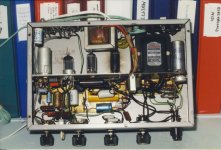
I managed to build the entire amp, tone controls, and preamp into a Hammond 8 × 12 × 3 chassis. Most of the major com*ponents are on a 3 × 12 sub-chassis inside. That includes the power supply, power amp, preamp, and tone circuits. I assembled the sub-chassis on the bench. The controls, input, and output connections are mounted on the front and rear panels of the chassis. These were all wired together at the final assembly stage.
Because there is some heat to be dis*sipated, I used a set of four 1˝ diameter ventilation hole plugs mounted on the ends of the chassis. There are several ½˝ holes in the bottom plate to allow cooling air in.
Around 1960 I built two other complete amps inside the larger Hammond 8 x 16 x 3 chassis. Both were running PP 25L6’s into Hammond 125D OPT’s. Other tubes in the lineup consisted of the regular 6SL7 type preamps & drivers. They were used by friends & never came back due to failures.
So far no electrolytic failures to report but something to consider in a poorly ventilated environment. The pages are from another era, need to be redone. For those who would prefer octals, 6SH7 & 6V6 are drop ins for this circuit.
I built this little amplifier back in 1968. Since then it has been used in quite a wide variety of locations. For the past few years it has been in my workshop. Program sourc*es are an Eico HFT-90 FM receiver and a matching Eico HFT-94 AM receiver. And sometimes a CD player.
The electronics is a FB pair consisting of a 6AU6 & 6AQ5 driving into a Hammond 125D OPT. The front end is a 12AX7 connected as a Baxandall tone circuit & another 12AX7 as a preamp for a low level magnetic phono pickup up or can be switched to a mike. DC is supplied by a FW SS rectifier driven by a Hammond 270AX transformer.
I managed to build the entire amp, tone controls, and preamp into a Hammond 8 × 12 × 3 chassis. Most of the major com*ponents are on a 3 × 12 sub-chassis inside. That includes the power supply, power amp, preamp, and tone circuits. I assembled the sub-chassis on the bench. The controls, input, and output connections are mounted on the front and rear panels of the chassis. These were all wired together at the final assembly stage.
Because there is some heat to be dis*sipated, I used a set of four 1˝ diameter ventilation hole plugs mounted on the ends of the chassis. There are several ½˝ holes in the bottom plate to allow cooling air in.
Around 1960 I built two other complete amps inside the larger Hammond 8 x 16 x 3 chassis. Both were running PP 25L6’s into Hammond 125D OPT’s. Other tubes in the lineup consisted of the regular 6SL7 type preamps & drivers. They were used by friends & never came back due to failures.
So far no electrolytic failures to report but something to consider in a poorly ventilated environment. The pages are from another era, need to be redone. For those who would prefer octals, 6SH7 & 6V6 are drop ins for this circuit.
Attachments
Perhaps something like this?I have a Tek PT with 3 150V secondaries, 2 smallish SE 5k:8 OPTs (antique supply P-T31) and a reasonable stash of tubes. (Pretty much all common noval preamp tubes in different flavors and a few different sets of power tubes like el84, el34, 6v6, 6550...) from what I remember of your cathode follower design, wouldn’t I need OPTs with a 600 ohm primary ? I would gladly try your design if it’s possible to make it work with the transformers I already have, but if not, I would prefer to use a circuit that better fits those parts.
Just an idea, not tested.
The 6V6 has to have a heater winding of it's own.
Mona
Attachments
May I ask where is that circuit from ? Do you have access to any other information about it ?
I will let the more experienced members comment about the actual circuit. It’s a cathode follower, it has silicone involved, something that looks like a doubler in the psu, so really high voltage, but I cannot say much more. Thanks for your input !
I will let the more experienced members comment about the actual circuit. It’s a cathode follower, it has silicone involved, something that looks like a doubler in the psu, so really high voltage, but I cannot say much more. Thanks for your input !
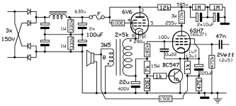
+630VDC raw supply.
+290VDC at the 6V6 cathode means the 6V6s absolutely must have their own heater supply lifted up to around +250V. That also means the 6SH7 (6SJ7) tubes must have a separate heater supply. Two separate 6.3v heater supplies. More complexity. Worth it?
+585VDC B+ to the 6SH7 (6SJ7). That's what enables it to swing a lot of signal volts out from its plate.
--
Does the heater supply absolutely need to be from another transformer or having multiple heater secondaries would do the job ?
The PS rectifier is simply a full bridge of SS diodes, nothing unusual except the very high & dangerous voltage.😱 The 6V6 is still connected as a triode so can swing the cathode no farther than it would swing the plate in a normal grounded cathode circuit.
A lot of cct for very ordinary results.🙂
A lot of cct for very ordinary results.🙂
A lot of cct for very ordinary results.🙂
I have to agree.
BTW, nice workshop system! The amp is really nice, and I love the EICO tuners. That stuff used to be everywhere, available for peanuts. Now it's collectors' gold. Times change...
The optimum load impedance for a given tube depends on it's peak current capability, it's ability to pull it's plate as close to the cathode voltage wise as possible, and the B+ voltage. The 6336 and a triode wired 6LW6 sweep tube both work best in the 200 to 250 volt range for B+ and have current capabilities in the 800 mA to 1.4 Amp range. This criteria is what drives the use of a 600 ohm OPT. 10 to 15 watts of triode SE cathode follower are possible. The limiting factor is the same as in most SE amps, the maximum tube dissipation.from what I remember of your cathode follower design, wouldn’t I need OPTs with a 600 ohm primary ?
Put a 6V6 in the same amp and that peak current capability drops to 105 mA, while the rated B+ voltage rises to 315 volts, and many users including Fender totally ignored this spec and went over 400 volts. This criteria predicates a 5K or higher OPT, but the maximum power output in SE triode is still about 2 watts from a 6V6.
The reason many people including myself experiment with cathode follower amps is that the voltage amplifier, and the current amplifier functions are now performed by two different tubes......What DEVICE would you use for the "best choice" for a current amplifier? The most important spec for the device in a follower application is Gm, so the logical choice would be a big fat MOSFET......uh, but I might get called Transistorlab again if I bring that up, but I tried it and it does work quite well. Just remember that the voltage across that part will swing to twice B+ in normal operation, and nearly 4X B+ in an overdriven guitar amp where the speaker is operated at or near it's resonant frequency. Use a 900 volt fet in a 170 volt amp, but use a 100 ohm OPT and get 25 watts. That required a BIG heat sink on that old Fuji mosfet (obsolete but still stocked at Allied).
This circuit comes from the 1940's. Leo Fender was trying to maximize the gain from the 6SJ7. The gain in a pentode is determined by the load impedance and the Gm of the tube. Gm varies with current, more current, more Gm.....more current requires more B+ voltage, or a lower load resistor which reduces gain. For any given tube there is only one combination of load resistor and current for maximum gain at any given B+ voltage......but there is a fairly wide range of "near maximum" gains with different combinations of load resistors and tube current.The 250k ohm plate resistor means it would drop 250V with only 1mA across it. With B+ of 350V this would leave only 100V at the 6SJ7 plate.......I was thinking the plate voltage should be more like 150V. With 3mA plate current, that would mean something like a 33k plate resistor to drop 100V, leaving 150V at the 6SJ7 plate. The screen grid load resistor might be something like 220k(?).
That old Fender circuit runs the 6SJ7 in near starvation to get maximum gain. This kills high frequency response since the output impedance is very high, and requires a high AC load impedance. This is why there is a 1 MEG volume pot despite the 500K maximum spec for grid circuit resistance in the 6V6 tube.
I prefer a more sane load resistor with a few mA of tube current. Need more gain, use a tube with higher Gm. The previously mentioned 6EJ7 is a good choice, but it's a 9 pin miniature tube. Other tricks can be used like bootstrapping the plate load so the tube sees a very high AC load. I have achieved stage gains of over 1000 with a 6AU6, but microphonics become the limiting factor in this case.
6AC7 is a good one, and keeps the metal tube vintage thing going.
I have collected a box full of metal tubes for a little MetallicAmp guitar amp project I plan to build.....All tube, no glass. I found 8 X new metal 6V6's in a box full of metal tubes that were about to be trashed at a hamfest several years ago. There are also 2X metal 6L6's, but they look well worn. Maybe 20 or so small signal tubes including some 6AC7's.
Attachments
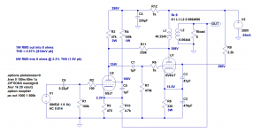
Okay, I'm not having an easy time with this. But here's what I have.
It doesn't try to DC couple. It's based on a 300V B+.
It looks like it's not going be a low distortion type of thing. LTspice says 0.57% THD at 1W out into 8 ohms, 1kHz. Not exactly hi-fi, and this is with both local plate-grid NFB and another 6dB of global NFB. Open loop THD is downright scary.
LTspice says max power is 5W into 8 ohms at 2.3% THD at 1kHz.
I don't know if this is good or not. It's the best I can seem to do at this point. I've attached the .asc file if anybody wants to play with it in LTspice.
I hope it's of some use.
Attachments
I built this little amplifier back in 1968. Since then it has been used in quite a wide variety of locations. For the past few years it has been in my workshop. Program sourc*es are an Eico HFT-90 FM receiver and a matching Eico HFT-94 AM receiver. And sometimes a CD player.
This is a really nice compact build ! I like the way you divided the enclosure in order to put the valves inside. I thought that side mounted valves could become an issue for some models, but it seems that you made it work considering the longevity of your amp ! Thanks for sharing !
The reason many people including myself experiment with cathode follower amps is that the voltage amplifier, and the current amplifier functions are now performed by two different tubes......What DEVICE would you use for the "best choice" for a current amplifier? The most important spec for the device in a follower application is Gm, so the logical choice would be a big fat MOSFET.....
First of all thanks for your detailed explanations. Most of the time, I learn a lot more by reading your comments than after spending an hour of googling and searching on the forums for an answer. Our hobby couldn’t get better without all that sharing.
Your comment makes me think of the PS Audio BHK 300 amplifiers. They use the devices where they (should) belong : tubes in the input as voltage amplifiers, and MOSFET outputs for current. Bascom H. King supposedly wanted to keep the tube advantages, but not being limited by their disadvantages. Those amps convinced famous speaker designer Arnie Nudell from genesis and infinity tube give up tune amps and get into solid state, even if he had used tubes for the vast majority of his life.
I will definitely use this. Kind of a nice way to get used to LTspice, wich has been installed on my computer for a year but never got used. Thanks for sharing !Okay, I'm not having an easy time with this. But here's what I have.
It doesn't try to DC couple. It's based on a 300V B+.
It looks like it's not going be a low distortion type of thing. LTspice says 0.57% THD at 1W out into 8 ohms, 1kHz. Not exactly hi-fi, and this is with both local plate-grid NFB and another 6dB of global NFB. Open loop THD is downright scary.
LTspice says max power is 5W into 8 ohms at 2.3% THD at 1kHz.
I don't know if this is good or not. It's the best I can seem to do at this point. I've attached the .asc file if anybody wants to play with it in LTspice.
I hope it's of some use.
6AQ5 6AU6 Amp THD Results
I just now noticed aside from the IMD plot the results of THD measurements missing from the 6AQ5 6AU6 are missing.😱 So here they are.🙂
I built this little amplifier back in 1968. Since then it has been used in quite a wide variety of locations. For the past few years it has been in my workshop. Program sourc*es are an Eico HFT-90 FM receiver and a matching Eico HFT-94 AM receiver. And sometimes a CD player.
I just now noticed aside from the IMD plot the results of THD measurements missing from the 6AQ5 6AU6 are missing.😱 So here they are.🙂
Attachments
Okay, I'm not having an easy time with this. But here's what I have.
I've been working on a spreadsheet to calculate plate to grid feedback (a la Schade and RDH4 7.2.v) and rongon's arrangement looks like an interesting way to use the tubes on hand. I'm getting about -12db local FB, effective 6V6 RP of 1600 ohms ish. Might be a good way to use the bargain bin OPTs.
I've been working on a spreadsheet to calculate plate to grid feedback (a la Schade and RDH4 7.2.v) and rongon's arrangement looks like an interesting way to use the tubes on hand. I'm getting about -12db local FB, effective 6V6 RP of 1600 ohms ish. Might be a good way to use the bargain bin OPTs.
Good to know ! I haven’t been able to use his spice simulation yet, due to some difficulties with adding the tube library to lt spice. No 6SJ7 in the tubecad program either, and didn’t have the time to find and add the specs of the tube into the program (datasheets specs don’t provide the same specs/units, and I don’t have a full understanding of the specs needed...)
A lot of learning to do at the same time. But if you guys all approve rongon’s schematic, i’ll build it as is and I will fine tune it as needed later on. Thanks for your input !
Last edited:
What voltage ratings should I use for C2, C3 and C4 ? I guess they have to be electrolytics, but I just want to clarify if I have to use a higher value than the B+ or if a lower value would do the job. Thanks !
Since the B+ supply is +300V, I'd make all caps 400VDC rated (or 350VDC absolute minimum), except for C2 (the 6V6 cathode bypass cap) which can be 50V or 63V.
I didn't give much thought to parts values. The sim is just a quick sketch. I'm sure it could be improved upon. I'll see if I can apply some tweaks to the simulation that make theoretical improvements.
--
PS - Let me know if you need tube models. I can send you some, or you can get almost anything from here.
Also, have you read through this thread? Vacuum Tube SPICE Models
--
One last thing... The most important part of an amp like this is the power supply. A pentode SE amp is going to be very sensitive to noise on the B+ supply. It would even benefit from voltage regulation, but that's basically building a whole other amplifier (a DC amp instead of an audio amp). At the very least, you want the B+ to be very well filtered with low ripple. Even that will require some effort and expense. Did you say you have a power supply filter choke available?
--
I've noticed in simulation that decreasing the value of the 'plate-to-plate' resistor (increasing the level of NFB) suppresses 2nd harmonic distortion in the output of the amp, but does not suppress 3rd harmonic as much. Unless the odd harmonics are already at a low level from the output stage, adding a lot of NFB results in a harmonic signature that looks like one from a push-pull pentode amp (more 3rd harmonic than 2nd harmonic generated). That sort of defeats the purpose of a single-ended amp, doesn't it?
--
I didn't give much thought to parts values. The sim is just a quick sketch. I'm sure it could be improved upon. I'll see if I can apply some tweaks to the simulation that make theoretical improvements.
--
PS - Let me know if you need tube models. I can send you some, or you can get almost anything from here.
Also, have you read through this thread? Vacuum Tube SPICE Models
--
One last thing... The most important part of an amp like this is the power supply. A pentode SE amp is going to be very sensitive to noise on the B+ supply. It would even benefit from voltage regulation, but that's basically building a whole other amplifier (a DC amp instead of an audio amp). At the very least, you want the B+ to be very well filtered with low ripple. Even that will require some effort and expense. Did you say you have a power supply filter choke available?
--
I'd be really interested to see that. Keep us posted, OK?I've been working on a spreadsheet to calculate plate to grid feedback (a la Schade and RDH4 7.2.v)...
I've noticed in simulation that decreasing the value of the 'plate-to-plate' resistor (increasing the level of NFB) suppresses 2nd harmonic distortion in the output of the amp, but does not suppress 3rd harmonic as much. Unless the odd harmonics are already at a low level from the output stage, adding a lot of NFB results in a harmonic signature that looks like one from a push-pull pentode amp (more 3rd harmonic than 2nd harmonic generated). That sort of defeats the purpose of a single-ended amp, doesn't it?
--
Here's a copy of the workbook.
I originally put it together to do E-Linear calcs, but converting the values for a traditional plate-grid FB network was straightforward (see RDH4 7.2.v). The FB/UL ratio and RL from the e-linear section determine the RL and Rfb in the common style circuit (bottom section).
There's also a separate set of calculations for a simple P-channel driver FB like SpreadSpectrum did on his KT88 PP amplifier.
Green cells are input values and orange cells are the formulas/calculations.
Let me know if any of the fields aren't clear. I made this for my use originally, so there's a bit of shorthand. Hopefully my equations are mostly correct 😛
Since the B+ supply is +300V, I'd make all caps 400VDC rated (or 350VDC absolute minimum), except for C2 (the 6V6 cathode bypass cap) which can be 50V or 63V. <snip>
For the power supply, I planned on using a 6H/200mA/150ohm choke and solid state rectifiers. Something like one good CLC filter, then to split the B+ with another rc filter for each channel. For those two filters, I wanted to go with small values like 1R/3uf to filter out the higher frequencies and feeding the amp with a high quality cap instead of an electrolytic. I’m getting used to psud2, I can post my design when it’s done.
For the spice model, i’ve downloaded the ayumi zip file, but haven’t been able to "install" so they are available in LTspice. I have read the first pages of the thread, looked on the internet, youtube videos, etc. I don’t seem to find anything about files with a .inc extension. All I can find is command lines that use the .include command. Maybe I’m missing something, i’ll have to put some time in this. I keep getting an error message on startup, telling me that 6V6_AN and 6SJ7_AN aren’t available.
Don't get hung up on the .inc extension. That's just for use with the .inc command ("include"), which you can use to stick a component model straight into a schematic as simple text.
Those Ayumi .inc files are 'subcircuit' models. Most other places you'll see these models created with the .sub extension. They're simple text files, so you could even save them with .txt extension (but that would be potentially confusing with all your other raw text files). The point is that these .inc files are called by the .asy 'symbol' file you select from the LTspice Component menu (when you click on the Component icon and choose from the dialog box). The 'symbol' .asy file (e.g., 6SJ7.asy) pulls the data from the 'subcircuit' .inc (or .sub) file (e.g., 6SJ7.inc) and stores it in your LTspice schematic's netlist.
The reason you're getting those errors that 6V6_AN and 6SJ7_AN aren't available is because I customize my models with different internal naming schemes than what's in the Ayumi_LTspice.zip models. My models won't match the Ayumi models without a bit of modification of both the .asy (symbol) files and their matching .inc (subcircuit) files.
It could also be that you're having trouble with the same thing I did back when I first tried to use LTspice. That is, I could not for the life of me create a symbol file (.asy) that worked with the .inc files in the Ayumi library. It's a multi-step process to make a 6SJ7.asy file that calls the 6SJ7.inc file correctly. When I get home I'll see if I can find some time to write up a tutorial on this, since I have another friend who wants to learn how to do this too.
In the meantime, here's a thread that has a LOT of really good tips for using LTspice for audio circuits.
Installing and using LTspice IV (now including LTXVII). From beginner to advanced.
Hopefully I'll be able to post something in a few hours.
--
Last edited:
Thanks a lot ! I’ll read this thread and see what I can do. I’ve spent a couple hours trying to get the tubecad program to run on my 64 bits computer, using virtual box and a windows xp sp3 iso file, understood how all this works, got rid of the error messages by creating a dummy printer so the program thinks it’s available, just to realize that the 6SJ7 isn’t in the models, and that it seems to only deal with triodes or triode connected pentodes. A lot of time and 20$ later i’m still at the same place....
Btw, do you intend on building this amp too or you just wanted to play with the design for fun ?
Btw, do you intend on building this amp too or you just wanted to play with the design for fun ?
- Status
- Not open for further replies.
- Home
- Amplifiers
- Tubes / Valves
- DC coupled single ended cathode follower 6SJ7/6V6 amp project