Notice that the schematic in post #123 has four silicon diodes in series; the max voltage from end-to-end is (4 x 0.95) = 3.8 volts. Electrolytic capacitors rated for "only" 6.3 volts, will work reliably in this application. Or you can choose capacitors with ANY voltage rating above 6V, basing your choice upon ripple current, size, and price. There's no special reason to use 63 volt capacitors.
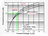
0.95 volts is the forward voltage drop of a Fairchild 35A, 600V bridge rectifier, part number GBPC3506, with ten amperes flowing (in the transformer primary)
_
0.95 volts is the forward voltage drop of a Fairchild 35A, 600V bridge rectifier, part number GBPC3506, with ten amperes flowing (in the transformer primary)
_
Attachments
Alex, so long as the capacitance values are correct;
First measure before the DC trap for DC. Confirm you have 1.8vDC. Now measure it in the middle of the diode bridge where the wire connects the two tabs (from that to neutral).
If you have 1.8vDC before, and 1.8vDC in the bridge, you've got an problem. Your capacitance and/or single diode bridge isn't enough. If you've got lower DC, like 1.2vDC on the bridge point, you're only dropping it .6vDC and you'd want to use probably three diode bridges. (And if it's .8vDC, use two bridges)
Here's the schematic.

I'm sorry my ignorance: why just 1.8VDC?
two diodes in series = 1V to 2V as the diode bypass turn on voltage
three diodes in series = 1.5V to 3V as the diode bypass turn on voltage.
For the DC blocker to be effective the diode must not turn on.
i.e. one must aim for the lower end of those ranges.
three diodes in series = 1.5V to 3V as the diode bypass turn on voltage.
For the DC blocker to be effective the diode must not turn on.
i.e. one must aim for the lower end of those ranges.
Last edited:
For example if I measure 4VDC before the mains transformer how can calculate the DC blocker?
What's the minimum VDC voltage before the mains transformers to don't need the DC blocker?
What's the minimum VDC voltage before the mains transformers to don't need the DC blocker?
Last edited:
The DC blocker does not actually block a DC offset. There is no DC to block. Thus no DC to measure.
It seems to be a filter that reduces the asymmetry in the AC waveform.
If you are reading 4Vdc, then I wonder what that reading is actually telling you.
It seems to be a filter that reduces the asymmetry in the AC waveform.
If you are reading 4Vdc, then I wonder what that reading is actually telling you.
If you don't hear any varying mechanical hum from the transformer, no need to fix this. If you are experiencing annoying hum which maybe vary also, then you'll need this filter.For example if I measure 4VDC before the mains transformer how can calculate the DC blocker?
What's the minimum VDC voltage before the mains transformers to don't need the DC blocker?
Toroidal transformers are more sensitive to this than normal EI cores.
Any idea what happens when I get nasty pops in the speakers if I plug something in the same outlet where the amp is plugged, and how can I prevent it?
fit a mains interference filter.Any idea what happens when I get nasty pops in the speakers if I plug something in the same outlet where the amp is plugged, and how can I prevent it?
Tried the .1 uF cap, better but I still get the noises. If I increase the capacitance, will there be any issue?
fit a mains interference filter.
An externally hosted image should be here but it was not working when we last tested it.
Tried the .1 uF cap, better but I still get the noises. If I increase the capacitance, will there be any issue?
Not until you get to a pretty high uf. Then you have to worry about discharge voltages within the amount of time one could unplug the device and appropriately place hands to receive juice.
Don't worry about say 2uf. Now if you got 100uf like Alex does, you need some discharge resistors.
Filtering and other
Great topic this is. One question I have as a beginner is: If one uses a filter like Nigel has proposedabove between the wall outlet and the transformer, is a CRC type filter still needed after the transformer and before the rectification. I ask this in reference to constructing a snubbered power supply for a chip amp.
Thanks for the help,
Myles
Post137 filter attenuates the mains interference.
You will still get interference that passes through and the cable from that first filter to your equipment enclosure will pick up more interference.
I would fit another "canned" mains filter at the enclosure cable entry.
You will still get interference that passes through and the cable from that first filter to your equipment enclosure will pick up more interference.
I would fit another "canned" mains filter at the enclosure cable entry.
Canned filter
Thanks for the info Andrew. If by "canned" you mean a brand name filter like Monster, I have one of these already.I use it for surge and filtering on my HT system. If some of the RF/EMI travels in thru the cables and this is joined by the noise from the transformer, would a CRC filter across the secondaries before the rectification take care of this. I am attempting to build as good as possible, a snubbered supply for a chip amp.
Thanks for the help,
Myles
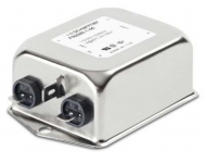
Canned means factory built in an all-metal enclosure which looks like a can. See attachment.
_
_
Attachments
Last edited:
Canned means factory builr in an all-metal enclosure which looks like a can. See attachment.
_
That's where my previous reply circuit came from.
I optimised the circuit for a 30 amp plastic welding machine to pass EMC standards. It passed very well.
An externally hosted image should be here but it was not working when we last tested it.
interference enters via EVERY cable that enters the enclosure.Thanks for the info Andrew. If by "canned" you mean a brand name filter like Monster, I have one of these already.I use it for surge and filtering on my HT system. If some of the RF/EMI travels in thru the cables and this is joined by the noise from the transformer, would a CRC filter across the secondaries before the rectification take care of this. ...............
If any of those cable are "exposed" inside the enclosure then they emit interference, especially if they are single cables/wires/traces rather than a flow and return pair.
You should trap interference at the cable entry.
That interference must be taken to the enclosure and thence by capacitance to "EARTH". It is this important route that requires the "canned" filter to be at the cable entry. This leaves no "exposed" cable before the filter and the can is bolted and/or electrically connected to enclosure to conduct the interference to EARTH.
- Home
- Amplifiers
- Power Supplies
- DC blockers and mains filters