That is a very good point. Many of these converters are actually specified to 3kV or even 5kV by the manufacturer.
Recom has units tested and specified to 15kV for medical applications.
But because of the way they are tested, consumer/legal organisations will not allow use at those levels because of liability issues.
One example is the HNCR200 analog optocoupler which should not be used over iirc 700Vac legally in products that you sell to consumers.
But it is specified by the manufacturer to like 5kV.
I have run them in a test with 4kV between input and output. I gave up after 120 hours of zero leakage.
So I feel confortable using them at 2kV.
Jan

I removed it and changed several other components to drive it with a mostfet amp I designed. Back in the late 80's this design it had no ouput inductors to prevent any high frequency resonance with the speaker load. Secondly it had a dc servo feedback to remove all dc offset at the output to prevent transformer core saturation. I somewhere read if you magnetize one of those big iron core tranformers, it requires serious AC current to demagnitize it. Otherwise the inductance goes down and it will seriously effect the low frequency coupling. I had a friend bring over and amp and it had 0.25V DC offset. You still had the big series resistor to prevent large current from flowing, but still.The 780uF N.P. (cheap) cap helps at 50 Hz but not much below that. I think purpose is to protect our amps when amp has to input low notes to the transformers. (The inductor in the input circuit helps massage the transformer at the high end.) While these DW transformers may the greatest ever, still quite a task covering so much band. My empirically derived input circuit is a bit different than Mike's but based on his design.
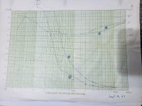
Attached is a graph of the impedance I measured of the speaker at the transformer input, at different primary impedance. I had it wired in parralllel and in series for different stepup ratios. It seems that the transformer had significant self inductance even at 30 Hz to prrovide an easy load on the amp.
Attachments
Any winding product, starting from the speaker coil with its magnet and diffuser and ending with the transformer, is the biggest EVIL in audio, therefore, in the case of using step-up transformers, it is better to approach electronic filters radically - use active electronic crossovers, otherwise you will have problems with high frequencies and saturation of the transformer iron, that is, cutting frequencies with a high order crossover in the right place.
Funny man, is it really that hard to measure with a hygometer?It's not that hard to diy either. 1500 V working voltage. 10 kV rated wire for neon lights.
View attachment 1339407
It seems that the transformer had significant self inductance even at 30 Hz to prrovide an easy load on the amp.
- If the impedance plot is measured at 2,83Veff (4Vpk) : same plot at 28,3Veff (40Vpk) will raise self inductance by factor 10 ( examplewise, depending on core material etc.) at low frequency < 500Hz.
- The 100Hz impedance peak is resulting from parallel resonance of self inductance as first contributor and net secondary capacitance stepped up by square of step up factor as the other contributor. Secondary capacitance is ~constant when voltage is changing.
- 100Hz impedance peak will go down in frequency by square root of the factor 10 : ~30Hz
- The curve above impedance peak frequency is "widely shifted to the left" and impedance is severely lowered there.
- Transformer primary midrange current will go up strongly with raising signal level in the base . This is not because saturated core. Maximum effect is when base and midrange level ( music ! ) is both present. Nasty load for the power amp !
- Huge amplifiers needed to charge internal transformer capacitance. Here primary - secondary capacitance will be a strong contributor ( big core ). To get an idea of the primary transformer capacitance : impedance plot of the transformer without electrostatic cells and then comparison to the loaded transformer curve.
- What could help : using the big Hammond transformer below midrange and taking a small core second second transformer for the rest of the audio bandwidth...see the soundlab approach attached..
- the parallel resonance itself is a big helper as current is lowered : real power fro the electrostatic cells is vanishingly low..
Attachments


Well it certainly is true that it required a huge amp to drive them. I have a Mosfet power amp similar in design to Hafler 280XL, but with =/- 74V rails for 6 output transistors per channel (3 parallel n and p channel) and +/- 82V for driving gain stage. It was enough to get comfortable volume. Now using same amplifier to drive ML electromotion speaker, my volume control is above off. Before it was way up. I like the ideas of transformer operation for low and high. I had an Accustat 2+2 loudspeaker for about 6 months in 1986, and it seemed much more efficient, but it also used two transformers. It did not sound nearly as good as my DW speaker, so I sold them.
- Home
- Loudspeakers
- Planars & Exotics
- Dayton-Wright ESL