This post is from last year, but I can't tell you how glad I am that I came across it!My ~4 years old SPA250 was not turning on and clicking of the power relay can be heard. I was about to write off this unit given all the horrible stories I read here and elsewhere, but I got bored one weekend and opened it up. Armed with the schematics of the amplifier section of a similar model I found on the net, I planned to measure power supply rails, but I never got that far. Turns out the power control board (to which I have no schematics) that detect audio and turn on the amp was attempting to turn on the amp and clicking the power relay. This board (photo attached) has a DC power supply that supply standby voltage (12V) to the preamp board. This power supply has a puffed capacitor "C8" (in the photo, it is the round black can with silver top left of the 3 pin molex connector). Replacing this cap with a salvaged cap (16V 470uF or larger) from a broken PC power supply repaired the unit. One would not expect electrolytic capacitors to fail so early, but I suspect Parts Express had these units on the shelf for years before selling them.
I was about to trash my sub because I didn't want to spend any money on it, to have it fixed by a repair shop, as it no doubt wouldn't have been worth it.
I combed through every component on the circuit boards, looking for signs of damage, such as blown or charred components, but didn't see any.
Low and behold, it was the same exact issue as described above: A puffed "C8" capacitor, which I had missed. $2.50 later (I replaced it with a Nichicon!), I have a working sub again. Thank you @WacGen!

Keeping an old thread alive here!
I also have 2 of these amps - actually HAD 4, but tossed 2.
The other 2 I still have both have failed for the umpteenth time. For those not familiar w/ southern american slang: they have failed more than a few times each.
Not only am I tired of fixing these un-reliable things, but the traces are lifting and becoming dificult-to-impossible to reliably fix.
The solution IMO is as another user stated: replacing the internal class a/b amp with a cheap class-d amp module readily available on eBay, Amazon, Ali Express, Mercado Libre and others.
Here is a link to the ones I just purchased:
https://articulo.mercadolibre.com.mx/MLM-1368826029-modulo-amplificador-clase-d-irs2092-500w-_JM
They will arrive end of next week sometime. Meanwhile - I have began mapping out the pre-amp board pinout and interface notes so that others here can do the same.
I plan to upload some pictures and detailed notes later this evening. I am lucky to have BOTH versions: the older one WITHOUT a physical relay and the newer one WITH a relay.
I have already bench-tested operation of the auto on/off circuit and pre-amp - WITHOUT the main amp board and am going to upload detailed notes tonight. This way, if someone wants to copy what I do, it will be easy. Likewise, if somebody wants to use/purchase a slightly different amp module, they should have all the info needed to wire it in.
Given the voltage rails already available by the dayton power supply, these modules will more/less retain the same power ratings at the originally rated speaker impedances. Some modifications are going to be needed - which I will outline in as much detail as possible.
Since these amp modules are typically less than $20, this is not just a cheap way of repairing these - but will also upgrade it a bit IMO and honestly... will likely be more reliable than the amp circuit these came with.
More to come...
My 3rd SPA250 Recently died. The 1st unit had the resistor problem and PE replaced it. The 2nd Amp was DOA. The 3rd amp played well for six years. A few days ago, I heard a popping sound every 5-20minutes. When I pulled the sub out, I noticed the Power LED cycling. I thought it was something in the Audio IN Sensing circuit. I pulled the amp and did not see any burned components or bulging capacitors. Nothing was obvious with a visual inspection.
The Amp was used continuously in "Auto Sense" mode for six years with no problems. After power up on the bench, the power relay cycled every 15 seconds in "Power ON" mode as no audio was available.. Power still cycled in Auto Sense (No audio inputted) and here is the biggie- it cycles power in the OFF position. Pretty sure that the ON-AUTO-OFF switch is suspect. Power definitely should not cycle in the OFF mode.
I have the older NHT schematic for the power board, but it does not match my board. The preamp and power relay schematics are missing. I have an O'Scope, sig gen and a component tester. Getting access to test points is difficult. Taking this beast apart will be a challenge. Any (new) documentation would be greatly appreciated. Otherwise, it means getting the octopus out and checking every component. Any advice is greatly welcome> Thanks- EVMan3
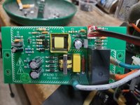
Another quick update. I took the Preamp and the Standby board out of the SPA250 amp for a better look. The Zener RS resistors are new 3k0 2W units. The filter cap bleeder resistors are also upgraded (R40, R41 3k0 2W). They have not discolored over six years, so it looks like a good fix. However, the capacitor that sits next to the Molex connector (labeled C8 on this version) is buckled. This a 16Vdc 470uF cap. The cap is on order now.
For what it's worth, pictures of the STANDBY and PRE boards are attached. Note the date codes of the PCB Artwork. I would still love to see some more documentation. Thanks to everyone who contributed, very much appreciated. EVMan
For what it's worth, pictures of the STANDBY and PRE boards are attached. Note the date codes of the PCB Artwork. I would still love to see some more documentation. Thanks to everyone who contributed, very much appreciated. EVMan
Attachments
You have the same symptom as my SPA250. C8 is the culprit. Standby voltage is low with a bad C8, which cause the Auto Sense circuitry to cycle and click the power relay. You can confirm this by measuring the voltage at the 3 pins connector (should be either 5V or 12V I don't remember).My 3rd SPA250 Recently died. The 1st unit had the resistor problem and PE replaced it. The 2nd Amp was DOA. The 3rd amp played well for six years. A few days ago, I heard a popping sound every 5-20minutes. When I pulled the sub out, I noticed the Power LED cycling. I thought it was something in the Audio IN Sensing circuit. I pulled the amp and did not see any burned components or bulging capacitors. Nothing was obvious with a visual inspection.
The Amp was used continuously in "Auto Sense" mode for six years with no problems. After power up on the bench, the power relay cycled every 15 seconds in "Power ON" mode as no audio was available.. Power still cycled in Auto Sense (No audio inputted) and here is the biggie- it cycles power in the OFF position. Pretty sure that the ON-AUTO-OFF switch is suspect. Power definitely should not cycle in the OFF mode.
I have the older NHT schematic for the power board, but it does not match my board. The preamp and power relay schematics are missing. I have an O'Scope, sig gen and a component tester. Getting access to test points is difficult. Taking this beast apart will be a challenge. Any (new) documentation would be greatly appreciated. Otherwise, it means getting the octopus out and checking every component. Any advice is greatly welcome> Thanks- EVMan3
Try a 25 or even 35V capacitor, or even a higher voltage if handy.
16V is too low for a 12V circuit in my opinion.
16V is too low for a 12V circuit in my opinion.
Hope everyone is well. My stuff from Amazon came in. I ordered 25Vdc, 470uF axial leaded caps. These fit if they are mounted standing up. I went to measure the voltages involved and my DVM was dead. After changing batteries, the DVM (Klein MM800) is still dead. Fortunately, my Amazon order included a Hantek 2D42 Scope-AFG-DVM Combo. The voltage across C8 was:
OFF = 0 Vdc
AUTO = 11.83 Vdc
ON = 12 Vdc (also routed to 3-Pin connector)
Hopefully, this is a good fix. I also measured ± 65 Vdc across the main filter caps. I suspect this will drop to around 55 Vdc under full load. So, it seems that the cap is a good fix. Probably my bad, but the +12 Vdc across C8 seems to have the positive voltage on the negative lead??!! Only one cup of coffee at this point, so it is probably user error on my part. A second set of eyes would help here . . .
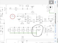
I also found the NHT SW10 preamp schematic. It is partially useful. If you look at schematic ZONES C1 and C2, you will see the 0N-AUTO-OFF switch and capacitor C26. C26 is rated 25 Vdc 470uF, but it looks like it is run from an 18 Vdc source.
The voltage on the 3-Pin connector was 12.0 or 11.83 Vdc and is connected directly to Cap C8. I really want to trace out the STBY circuit board. However, Led Zep is awaiting. Please keep this thread alive with more comments, suggestions or tales of amps catching fire (three found so far). Many thanks to WacGen for finding and reporting this. Best Regards- EVMan
OFF = 0 Vdc
AUTO = 11.83 Vdc
ON = 12 Vdc (also routed to 3-Pin connector)
Hopefully, this is a good fix. I also measured ± 65 Vdc across the main filter caps. I suspect this will drop to around 55 Vdc under full load. So, it seems that the cap is a good fix. Probably my bad, but the +12 Vdc across C8 seems to have the positive voltage on the negative lead??!! Only one cup of coffee at this point, so it is probably user error on my part. A second set of eyes would help here . . .
I also found the NHT SW10 preamp schematic. It is partially useful. If you look at schematic ZONES C1 and C2, you will see the 0N-AUTO-OFF switch and capacitor C26. C26 is rated 25 Vdc 470uF, but it looks like it is run from an 18 Vdc source.
The voltage on the 3-Pin connector was 12.0 or 11.83 Vdc and is connected directly to Cap C8. I really want to trace out the STBY circuit board. However, Led Zep is awaiting. Please keep this thread alive with more comments, suggestions or tales of amps catching fire (three found so far). Many thanks to WacGen for finding and reporting this. Best Regards- EVMan
Attachments
I designed an "Econowave" type 2-way speaker. The SPA250 is connected to the STLF12120A driver for break in. I should probably plot a frequency response curve for the infrasonic filter . . . The Hantek 2D42 (Not true RMS) Scope-DVM-AFG worked well in place of the Klein MM700. After re-assembly, the Klein 700 was troubleshot to the main selector switch. The wiper is part of the switch, but the contacts are gold-plated PC Traces on the circuit card. Cleaned them with Caig Labs Cramolin. Everything seems to be working now. Time to clean up the old Pace unit. Thank you all again. Cheers- EVMan
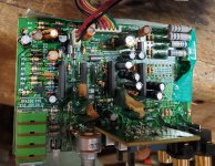
Glad I found this thread. I have the Dayton SPA250 plate amp and I also have the issue of the auto senseing ect. clicking on and off. I am posting 2 images. The first is the board has the connections. Is that cap circled in yellow blown? in the second image is the c8 cap, is that blown as well? Any help is appreciated. Thank you.


C8 in your 2nd photo is the one I replaced. The one in your 1st photo looks suspicious, but I would replace C8 first and see if that fix your problem.
Put higher voltage caps, 16V on a 12V line is close.
But please check if they will fit, the higher voltage caps may be of larger diameter.
See for 25 / 35 / 63V, and change them out.
And see if the good ones are also cheapo Chinese stuff, you can replace with standard quality caps from a reputed maker.
You might find 47 / 1000 / 1500 / 2200 uF in 16V from an old motherboard...Gigabyte for one uses Japanese caps, mostly undamaged on blown boards!
Very useful for such repairs...
Good morning guys. I noted the C8 Cap manufacturer as ChengX, 16 Vdc at 470uF. I have been in electronics for forty years and never heard of that brand. C8 is definitely bad. The cap on your first photo is also suspect. WacGen is the Man who deserves the credit. Great job. My amp is repaired and burning in my low frequency driver. No more problems to report after replacing C8.
I can get the C8 cap on Amazon (it’s listed as a bestseller), can anyone tell what the other cap is that’s in pic #1?
is the correct orientation of replacement having the gray mark on the edge of the cap end facing down like all the similar ones seem to be?
Please bare with me as I go through this. Thank you.
is the correct orientation of replacement having the gray mark on the edge of the cap end facing down like all the similar ones seem to be?
Please bare with me as I go through this. Thank you.
Hi Freerojo, sounds like you are in the home stretch. Capacitors usually hard fail with a short (resistors open). Before failing completely, caps can act wonky. The caps can exhibit an extraordinary array of symptoms. If you even suspect, a capacitor problem - replace it.
All electrolytic caps are marked somehow. The gray or black band has a "Minus sign" imprinted on it. Obviously, the polarity must be observed. My "go to" caps are Panasonic or Nichon. I replaced the wonky cap with a 25 Vdc unit. Capacitor size increases with higher working voltages. Since space is tight, I used an axial leaded component instead of the original radial leaded cap. When designing circuits from scratch, a safety margin of 4:1 ensures long life. Designs with less than 2:1 will eventually fail IMHO. Good luck and good listening.
All electrolytic caps are marked somehow. The gray or black band has a "Minus sign" imprinted on it. Obviously, the polarity must be observed. My "go to" caps are Panasonic or Nichon. I replaced the wonky cap with a 25 Vdc unit. Capacitor size increases with higher working voltages. Since space is tight, I used an axial leaded component instead of the original radial leaded cap. When designing circuits from scratch, a safety margin of 4:1 ensures long life. Designs with less than 2:1 will eventually fail IMHO. Good luck and good listening.
I think the capacitor that is puffed in pic #1 is this one https://www.amazon.com/Projects-Radial-Electrolytic-Capacitor-22uF/dp/B07XYGCBXR Could someone confirm this for me?
Free Rojo, my apologies if I left you hanging. My amp is back in the subwoofer cabinet, so I cannot confirm. All is not lost. Simply remove the suspect cap and read the Wvdc and capacitance in uF marked directly on the component. . . You can upgrade the voltage rating and capacitance values if they will fit in the allocated real estate. Replace with the same value or better, never go lower. My go to for components is usually Digi Key or Mouser. Amazon is easy but expensive. More questions? Always feel free to ask. These forums are a wealth of information.
Both caps look bad. The first pic has J30 labelled with the bulging cap below. I can read 25 WVDC on the case but not the capacitance . . .
That cap is used for decoupling the power supply from the amplifiers. The absolute value is not critical, but a wonky cap here would be a disaster. In this case I would recommend a 35 Vdc 220uF Cap. 105C is the temperature rating during operation. If you go capacitor shopping, look for the Lowest ESR and a minimum of 105C. Tantalum caps will have the lowest ESR in this volume. To gild the lily, you could add a non-inductive solid film .22uF cap. in parallel. Polypropene, mylar, etc. The larger value 220uF cap will handle the low frequency noise and ripple, while the .22uF cap will handle the higher frequency noise. If you look at the impedance curves, you will note rising impedance vs. frequency for the electrolytic, while the solid dielectric cap has relatively flat impedance across the band. Good luck- EVMan
- Home
- Loudspeakers
- Subwoofers
- Dayton SPA250 Plate Amplifier repair help