Good question. Of the three DACs you mention, TDA1541 is potentially the easiest as its output terminal is designed to sit at GND potential. The possible challenge with it is - there will be some devices which put out too much current (the max is 4.6mA) which might lead to clipping. The nominal 4mA is perfectly OK though. To use the 1541 straight into the Dark LED only needs including a positive current source of 2mA connected to the output as its natively a unipolar DAC. Philips in their CD players typically implement the CCS with a resistor to the +15V rail, decoupled with a cap to attenuate supply noise.
Seeing as the other two don't include GND in their output voltage compliance I need to have a bit of a think as to how to get them to work. Some kind of level shifter will be needed. I'll come back and update when I have an idea how to do this. If anyone else has an idea, do please share.
Seeing as the other two don't include GND in their output voltage compliance I need to have a bit of a think as to how to get them to work. Some kind of level shifter will be needed. I'll come back and update when I have an idea how to do this. If anyone else has an idea, do please share.
Having reflected on this, the simplest solution, which will work for both TDA1545 and TDA1543 is to change R10 (0R) for a BZX84C3V0 zener diode. Cathode of zener (centre pin of SOT-23) towards Q7.
This mod will set the input voltage of Dark LED to +3V (as opposed to 0V for the stock version). +3V suits both these two DAC chips. For TDA1545 it will be best to set the total output current swing to 2mA through the use of 2 * 11k resistors from VDD to pin7. TDA1543 already has enough swing, just its offset will need adjusting via pin7.

This mod will set the input voltage of Dark LED to +3V (as opposed to 0V for the stock version). +3V suits both these two DAC chips. For TDA1545 it will be best to set the total output current swing to 2mA through the use of 2 * 11k resistors from VDD to pin7. TDA1543 already has enough swing, just its offset will need adjusting via pin7.

Withe this set up, is there any audible sound penalty ?Having reflected on this, the simplest solution, which will work for both TDA1545 and TDA1543 is to change R10 (0R) for a BZX84C3V0 zener diode. Cathode of zener (centre pin of SOT-23) towards Q7.
This mod will set the input voltage of Dark LED to +3V (as opposed to 0V for the stock version). +3V suits both these two DAC chips. For TDA1545 it will be best to set the total output current swing to 2mA through the use of 2 * 11k resistors from VDD to pin7. TDA1543 already has enough swing, just its offset will need adjusting via pin7.
View attachment 1158613
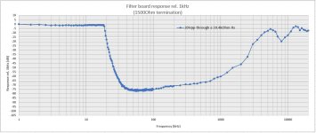
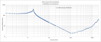
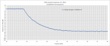
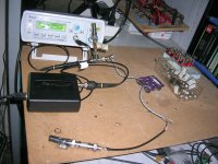
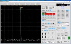
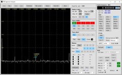
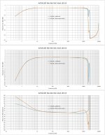
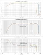
Here is the last of the data I have collected for the stand-alone 9th order filter board.
Filter's Frequency response rel 1kHz and Filter's Input Impedance Modulus.
Termination of filter at 1500 Ohm
20Vpp signal in series with a 39400 Ohm to approximate current drive.
The output of the filter at the filter's cut-off frequences is very low with such a signal drive. The oscilloscope couldn't resolve those signals. I had to use an SDR dongle (SDRplay RSP1A) as the signal detector and an RF FFT SW for reading the signal in dBs. This SDR operates from as low as 1kHz but not as good as from 10kHz and up. This for the frequency response measurement.
For the Zin measurement, signal levels were higher (voltage upstream and downstream of the 39.4k Rs), so I used the oscilloscope for level measuring.
Point to point manual method, 226 test points on both.
George
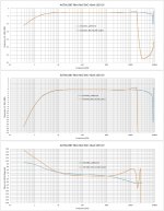
Attachments
-
 Filter Response Current drive.jpg132 KB · Views: 92
 -
 Filter impedance Current drive.jpg90.2 KB · Views: 91
 -
 Filter Response Current drive (Zoom-in).jpg144.5 KB · Views: 111
 -
 Zin test.JPG571.2 KB · Views: 101
 -
 FR test.JPG591.7 KB · Views: 90
 -
 input 800kHz.jpg201.2 KB · Views: 95
 -
 output 800kHz.jpg173 KB · Views: 97
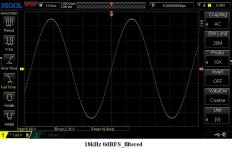
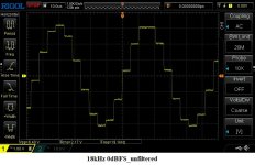
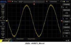
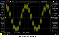
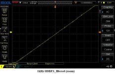
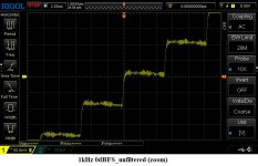
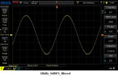
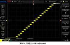
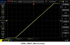
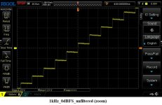
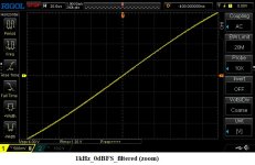
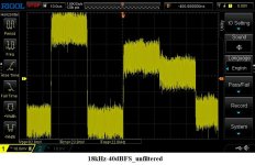
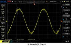
Hi AbraxHere is how an 18kHz sinewave looks on a typical very-lightly filtered NOS DAC, compared to the filtered output of 'Dark LED' reproducing the same signal:
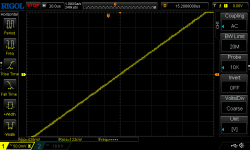
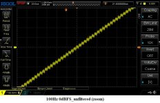
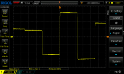
Using your Mini Ref. DAC (4xTDA1387) and the Dark Led I/V board, here is what I could see at the analog out (10kOhm load) with/without the 9th order filter.

")
George
Attachments
-
 18kHz_0dBFS_filtered.jpg98.1 KB · Views: 84
 -
 18kHz_0dBFS_unfiltered.jpg96.5 KB · Views: 81
 -
 18kHz-40dBFS_filtered.jpg102.5 KB · Views: 84
 -
 18kHz-40dBFS_unfiltered.jpg108.6 KB · Views: 85
 -
 1kHz_0dBFS_filtered(zoom).jpg94.7 KB · Views: 74
 -
 1kHz_0dBFS_unfiltered(zoom).jpg96.3 KB · Views: 78
 -
 100Hz_0dBFS_filtered (zoom).png13.7 KB · Views: 80
 -
 100Hz_0dBFS_unfiltered (zoom).jpg98.8 KB · Views: 90
And I wondered how my DAC's raw results were better than yours.Your 18kHz sinewave already looks like a sinewave before its filtered George. So I figure (by counting the steps on the waveform) you must be running at 4X OS.

Thank you Abrax
It was 192kHz(48kx4) /24bit instead of the 44.1kHz/16bit I had set in REW.
Windows intervenes, overtaking the settings in REW and despite the selection of exclusivity control within Windows.
Needs manual setting (open: sound settings/sound control panel/playback/USB2…/Properties/Advanced/16/44.1/Apply).
Now, all over again (44.1kHz/16bit).
George
Attachments
-
 18kHz_0dBFS_filtered.jpg98 KB · Views: 63
 -
 100Hz_0dBFS_unfiltered (zoom).jpg96.2 KB · Views: 64
 -
 100Hz_0dBFS_filtered (zoom).jpg95.8 KB · Views: 66
 -
 1kHz_0dBFS_unfiltered (zoom).jpg94.2 KB · Views: 61
 -
 1kHz_0dBFS_filtered (zoom).jpg96.3 KB · Views: 56
 -
 18kHz-40dBFS_unfiltered.jpg106.2 KB · Views: 66
 -
 18kHz-40dBFS_filtered.jpg102.6 KB · Views: 69
 -
 18kHz_0dBFS_unfiltered.png11.8 KB · Views: 66
Last edited:
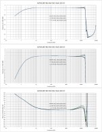
I took some FR sweeps of the Mini Ref. DAC (4xTDA1387) + Darl LED I/V (output load 10kOhm) with and without the 9th order filter.
Signals of 44.1kHz/16bit, 88.2kHz/16bit, 176.4kHz/16bit, 0.2dBFS were generated in REW.
The USB to I2S receiver (CM6631A) was the output device, each time set to one of those formats. The EMU 0404 sound card was the input device set to 192kHz/24bit.
George
Signals of 44.1kHz/16bit, 88.2kHz/16bit, 176.4kHz/16bit, 0.2dBFS were generated in REW.
The USB to I2S receiver (CM6631A) was the output device, each time set to one of those formats. The EMU 0404 sound card was the input device set to 192kHz/24bit.
George
Attachments
Are you using the SDRplay as a spectrum analyzer (SA) because you don't have a dedicated SA? Or a mixed-domain FFT feature in common Rigol, Siglent or Owon 'scopes?The output of the filter at the filter's cut-off frequences is very low with such a signal drive. The oscilloscope couldn't resolve those signals. I had to use an SDR dongle (SDRplay RSP1A) as the signal detector and an RF FFT SW for reading the signal in dBs. This SDR operates from as low as 1kHz but not as good as from 10kHz and up. This for the frequency response measurement.
BTW: interesting -- and potentially useful -- that the SDRplay is spec'd for freqs as low as 1khz. I assume it has reasonable accuracy, fidelity and (most important) repeatably at that low freq. If so, might be a viable alternative to Audio Precision models.
HiAre you using the SDRplay as a spectrum analyzer (SA) because you don't have a dedicated SA?
Yes. I don't have a dedicated SA.
This I have but it is hampered by the inadequate (for the case) sensitivity of the oscilloscope itself, not to mention the poor functionality of these FFTs. I can say it is only for visual overview of the freq spectrum.Or a mixed-domain FFT feature in common Rigol, Siglent or Owon 'scopes?
Sensitivity varies with frequency (please see the attached detailed spec sheet) but I used it in 'quasi differential' mode by measuring filter input and output, therefore this varying sensitivity issue was made irrelevant. Otherwise I had to use the sensitivity charts and compensate accordingly (not accurate results)I assume it has reasonable accuracy, fidelity and (most important) repeatably at that low freq.
The repeatability is superb.
George
Attachments
Cool!Sensitivity varies with frequency (please see the attached detailed spec sheet) but I used it in 'quasi differential' mode by measuring filter input and output, therefore this varying sensitivity issue was made irrelevant. Otherwise I had to use the sensitivity charts and compensate accordingly (not accurate results)
The repeatability is superb.
Yes, the cheap MDOs are not ideal for SA because they extrapolate spectrum by performing FFT math (in the "software domain" ) . So not true SA in that a dedicated hardware device isn't used.
I have a TinySA Ultra and NanoVNA. A bit disappointment with those -- reliability and usability issues - - but they are low-cost, like SDRPlay.
Sorry for going OT, folks.
Hello,
I've been following this from the beginning and I think it's an awesome design! However, it seems it won't work with my DAC, a DDDAC clone. So, I'll have to ask a couple of questions, hopefully not disturbing this nice thread.
First, the DDDAC cannot take a 1k5 I/V resistor, more like 150 ohm will do but can the LC filter be terminated to such a low resistance? Could I simply put the 150 ohm I/V resistor right after the current amp and leave the filter terminated to 1k5?
Another thing is that my DAC holds two sections, one oversampling and one NOS working independently and the output is selected with relays. But the outputs that are not connected should be terminated to a resistor and for practical reasons these resistors have to stay on all the time. So, if you are still following, the question is if the current amp is OK to see a shunt resistor and what would be the minimum value that would not disturb the circuit? I'm afraid I won't like the answer to this but anyway...
Is your DDDAC the one based on PCM1794 or TDA1543?
The I/V resistance seen by the DAC isn't 1k5, that's what determines the current/output voltage ratio for Dark LED. The DAC sees the input resistance of a common-base stage and that's in the region of 5ohm. This is an active I/V circuit, not a purely passive I/V with a filter added on.
As regards adding a shunt resistor, normal R2R DACs have internal shunt resistors of the region of 1kohm. Another way of looking at that shunt resistor is - its the output impedance of the DAC chip. Its OK to add a shunt resistor - I have used a shunt resistor in conjunction with a series R myself as a way to reduce the effective output current of an array of TDA1387 DACs. I think 150ohm would not cause a major disturbance but I would hesitate to go any lower in value than that.
Abraxalito, thank you for answering.
It is PCM1794. Not an R2R for that matter. Output would be 1,2V with 133 ohm resistor I/V. Could your circuit be adjusted for this?
I guess 150 ohm doesn't stress PCM1794. And should I assume that it will not degrade the Dark LED I/V? Is it going to be 150||5 ohm?
It is PCM1794. Not an R2R for that matter. Output would be 1,2V with 133 ohm resistor I/V. Could your circuit be adjusted for this?
I guess 150 ohm doesn't stress PCM1794. And should I assume that it will not degrade the Dark LED I/V? Is it going to be 150||5 ohm?
The PCM1794 DS says it puts out 7.8mA p-p, on each of its 4 output pins. That means each output is 3.9mA peak which is about 6dB too hot for Dark LED. You can reduce the current with a series and shunt combination of resistors provided the DAC output compliance isn't exceeded. Or you could limit your digital volume to -6dB max.
- Home
- Vendor's Bazaar
- Dark LED passive filter-I/V stage for NOS DACs