And it's even hotter than your calculations as Doede Douma has pushed it further from app notes. Clearly this DAC was designed with passive I/V in mind and it works very well with this. Actually, it is your filter that I want to add somehow. And a full Dark LED for a future R2R DAC. I'll keep following this thread with great interest. Thank you!

It is the best solution, no doubt. Is it as simple as changing components or PCBs have to be redesigned? The reason I ask is that I need to keep the balanced outputs without intermediate conversions so the obvious for me was a double built despite space limitations. Anyway, the final criterion will be cost since these days are tough for hobbyists... I need to know how much to start saving. If you think it's better to PM let me know.
If you want to keep your balanced outputs then I guess you would need 4 channels of filtering. The filters I currently have PCBs for are for two channels so you'd need two. Also my filters are designed to plug into my DAC (and I/V) boards with 2mm pitch connectors but I very much doubt that connection method would suit your existing DDDAC. So some PCB customization would probably be appropriate.
Cost will depend mostly on how steep a filter you need, you might find 5th order is good enough (for example) rather than going all the way to 9th order. I already have a 5th order filter design for I/V resistor of 110R which might be suitable.
By all means PM me if you'd like to discuss this further.
Hi Gaetano - The DAM1021 as I understand it is a voltage out, discrete R2R design. So it could only be used with a V/I converter stage prior to the Dark LED. The V/I converter could be a buffer (unity gain amp) followed by a resistor.
As to what it does - it does the I/V function for a current-out DAC and includes steep passive filtering to reject image frequencies which are necessarily generated by NOS DACs.
As to what it does - it does the I/V function for a current-out DAC and includes steep passive filtering to reject image frequencies which are necessarily generated by NOS DACs.
In post #73, I showed some FR measurements without and with the 9th order filter and using 44.1kHz, 88.2kHz, 176.4kHz sweep signals.
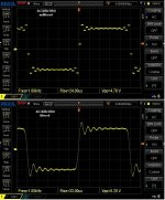
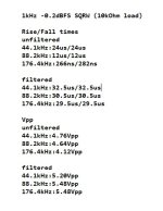
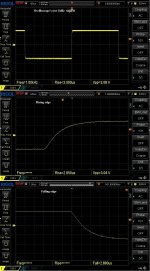
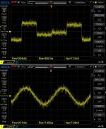
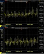
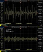
Now, the same setup, this time feeding a 1kHz square wave, 0.2dBFS.
Screenshots from a 200MHz Oscilloscope, and a 350MHz probe (x10)
10kOhm output load.
George
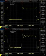
Now, the same setup, this time feeding a 1kHz square wave, 0.2dBFS.
Screenshots from a 200MHz Oscilloscope, and a 350MHz probe (x10)
10kOhm output load.
George
Attachments
Hi George,And I wondered how my DAC's raw results were better than yours.
Thank you Abrax
It was 192kHz(48kx4) /24bit instead of the 44.1kHz/16bit I had set in REW.
Windows intervenes, overtaking the settings in REW and despite the selection of exclusivity control within Windows.
Needs manual setting (open: sound settings/sound control panel/playback/USB2…/Properties/Advanced/16/44.1/Apply).
Now, all over again (44.1kHz/16bit).
George

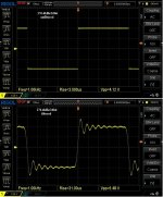
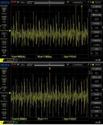
I could use some help to understand why the waveforms at -40dB seem blurred/noisy compared to 0dBFS.
Χρόνια Πολλά!
Hi MagicBus
The easy way out to your very good question is that the oscilloscope vertical resolution is only 1V/div for the 0dBFS signal but it is 10mV/div for the -40dBFS signal, i.e. this noise is present over the 0dBFS waveform as well but it doesn't show.
Of course the question would have been “What’s that bloody noise in your signals George?” weren’t you that polite") .
.
The answer will be “it’s digital switching noise”.
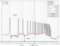
For illustration purposes, 1st to 10th attachments:
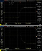
Is a series of oscilloscope screenshots (same vertical resolution, increasing time resolution) of the -40dBFS 18kHz (44.1k/16bit) signal unfiltered (upper trace) and filtered (lower trace).
This is from probing the analog out of the Dark LED across a 10kOhm load.
It is obvious from the start that filtered and unfiltered signals are equally afflicted by the the HF noise. Noise pattern and peak amplitude is the same on both. In 7th to 10th screenshots (higher freq content details) , the filtered signal is more noisy than the unfiltered one.
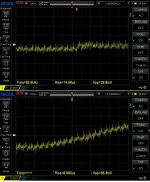
Hint one. HF noise bypasses the LP action of the filter board.
Hint two. At higher RF frequencies, the filter seems to amplify the noise.
The freq response and input impedance of the passive filter I have shown in post #68 are up to 20MHz.
What is shown here in this post (*) is RF content, mostly at still higher frequencies. The rising edges of strong spurae waveforms reach the 1ns rising time, suggesting frequencies at and above 350MHz, (above the oscilloscope BW).
The 9th order filter is a passive filter, so amplified HF signals suggest either a resonance peak or simply the additional PCB area acting as one more efficient receiving antenna for airborn noise.
The 11th attachment shows:
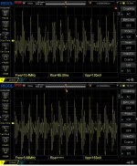
On the upper trace the noise in idle (that is with a silent DATA line but active LRCK and BCK I2S lines). Noise pattern and amplitude is the same as with the noise when 18kHz signal is present (compare with the 9th attachment).
On the lower trace, the noise pattern has become more even and amplitude reduced. This is when the USB cable is disconnected, or when the USB to I2S board is unpowered, or when all boards are unpowered, that is, the passive pick-up of the environmental RF pollution, which is somewhere around 100MHz, consistent with the higher RF content in my area due to proximity (5kM away) of FM Radio stations transmitting antennae.
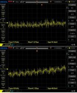
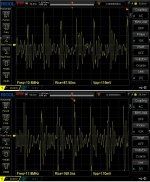
12th attachment is is an FFT with a sniffer M probe over the test area, when everything is unpowered. Notice the clutter at the broadcasting band (88MHz to 108MHz)
George
(*) All these noisy (SNR:4dB) oscilloscope screenshots are broadband measurements, 200MHz scope, 350MHz probe x10. Restricting the measurement BW to 20MHz, cuts the HF spurae by two (SNR:10dB). With 100kHz measurement BW, noise is almost non existent (SNR:68-69dB)
The easy way out to your very good question is that the oscilloscope vertical resolution is only 1V/div for the 0dBFS signal but it is 10mV/div for the -40dBFS signal, i.e. this noise is present over the 0dBFS waveform as well but it doesn't show.
Of course the question would have been “What’s that bloody noise in your signals George?” weren’t you that polite
.The answer will be “it’s digital switching noise”.
For illustration purposes, 1st to 10th attachments:
Is a series of oscilloscope screenshots (same vertical resolution, increasing time resolution) of the -40dBFS 18kHz (44.1k/16bit) signal unfiltered (upper trace) and filtered (lower trace).
This is from probing the analog out of the Dark LED across a 10kOhm load.
It is obvious from the start that filtered and unfiltered signals are equally afflicted by the the HF noise. Noise pattern and peak amplitude is the same on both. In 7th to 10th screenshots (higher freq content details) , the filtered signal is more noisy than the unfiltered one.
Hint one. HF noise bypasses the LP action of the filter board.
Hint two. At higher RF frequencies, the filter seems to amplify the noise.
The freq response and input impedance of the passive filter I have shown in post #68 are up to 20MHz.
What is shown here in this post (*) is RF content, mostly at still higher frequencies. The rising edges of strong spurae waveforms reach the 1ns rising time, suggesting frequencies at and above 350MHz, (above the oscilloscope BW).
The 9th order filter is a passive filter, so amplified HF signals suggest either a resonance peak or simply the additional PCB area acting as one more efficient receiving antenna for airborn noise.
The 11th attachment shows:
On the upper trace the noise in idle (that is with a silent DATA line but active LRCK and BCK I2S lines). Noise pattern and amplitude is the same as with the noise when 18kHz signal is present (compare with the 9th attachment).
On the lower trace, the noise pattern has become more even and amplitude reduced. This is when the USB cable is disconnected, or when the USB to I2S board is unpowered, or when all boards are unpowered, that is, the passive pick-up of the environmental RF pollution, which is somewhere around 100MHz, consistent with the higher RF content in my area due to proximity (5kM away) of FM Radio stations transmitting antennae.
12th attachment is is an FFT with a sniffer M probe over the test area, when everything is unpowered. Notice the clutter at the broadcasting band (88MHz to 108MHz)
George
(*) All these noisy (SNR:4dB) oscilloscope screenshots are broadband measurements, 200MHz scope, 350MHz probe x10. Restricting the measurement BW to 20MHz, cuts the HF spurae by two (SNR:10dB). With 100kHz measurement BW, noise is almost non existent (SNR:68-69dB)
Attachments
-
 1-50us.jpg222.8 KB · Views: 80
 -
 2-20us.jpg210.7 KB · Views: 77
 -
 3-10us.jpg206.6 KB · Views: 73
 -
 4-5us.jpg201.2 KB · Views: 69
 -
 5-2us.jpg197 KB · Views: 69
 -
 6-1us.jpg202.9 KB · Views: 69
 -
 7-500ns.jpg214 KB · Views: 74
 -
 8-200ns.jpg231.2 KB · Views: 65
 -
 9-100ns.jpg222.9 KB · Views: 73
 -
 10-50ns.jpg218.6 KB · Views: 77
 -
 11-idle and USB N-C.jpg215.3 KB · Views: 78
 -
 12-small sniffer probe over test area.jpg213.9 KB · Views: 83
You are welcome. You are a clever and polite participant, a person good to exchange posts with.
I do these tests for myself, in the process of working toward better PSUs for the DAC system.
It seems that first I have to take measures for to encase/shield the digital section and the I2S lines.
The rise time on the I2S switching waveforms is 1ns to 1.5ns (>200MHz noise spitters).
George
I do these tests for myself, in the process of working toward better PSUs for the DAC system.
It seems that first I have to take measures for to encase/shield the digital section and the I2S lines.
The rise time on the I2S switching waveforms is 1ns to 1.5ns (>200MHz noise spitters).
George
Polite with good people and clever enough to understand why advanced equipment is not for me...
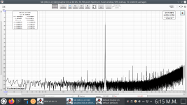
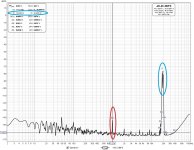
I'll be following your work. Just to add the need for filtering the ultrasonic images. Two simple graphs in NOS mode, one at 48kHz and one at 192kHz that convinced me I need Abraxalito's Celibidache filter.
I'll be following your work. Just to add the need for filtering the ultrasonic images. Two simple graphs in NOS mode, one at 48kHz and one at 192kHz that convinced me I need Abraxalito's Celibidache filter.
Attachments
Hi MagicBus
It may sound as heretical to you, but IMO measurements is one thing, listening impressions is another.
I have auditioned this DAC set, filter-less for a week. There are differences in the timbre, sharpness and detail resolution compared to the filtered DAC but there is no noise, no harshness, no fatigue. I have HF hearing loss and at the same time hypersensitivity to anything in excess at HF.
If your pre/power amps past the DAC do not misbehave due to ultrasonic content, you may find the DAC sound without filter or lightly filtered not that bad.
George
Hi George,
Generally, I agree that listening will be the final test. My speakers won't go over 17kHz and ears stop at 16kHz. And it was this thread https://www.diyaudio.com/community/...makes-nos-sound-different.371931/post-6643742 that helped me understand that ultrasonic images per se do not make any audible difference. Besides, I have been listening to my unfiltered NOS DAC for a long time and fatigue is the last thing I would say about it. But IMD is present no doubt and I would like to have a test with the filter for comparison. In the graphs posted above, IMD should be the product of my soundcard's input. There the ADC is supposed to use digital anti-aliasing filter so the reasonable conclusion is that it all happens in the analog buffer in front of it. This consists of a OPA1656 in unity gain followed by a fully compensated OPA1632 monolithic differential opamp and yet it can't cope. Or at least that's how I understand it. It would be interesting to see if the filter can remove IMD and make any audible difference. FWIW I'm trying to include a bypass function.
Generally, I agree that listening will be the final test. My speakers won't go over 17kHz and ears stop at 16kHz. And it was this thread https://www.diyaudio.com/community/...makes-nos-sound-different.371931/post-6643742 that helped me understand that ultrasonic images per se do not make any audible difference. Besides, I have been listening to my unfiltered NOS DAC for a long time and fatigue is the last thing I would say about it. But IMD is present no doubt and I would like to have a test with the filter for comparison. In the graphs posted above, IMD should be the product of my soundcard's input. There the ADC is supposed to use digital anti-aliasing filter so the reasonable conclusion is that it all happens in the analog buffer in front of it. This consists of a OPA1656 in unity gain followed by a fully compensated OPA1632 monolithic differential opamp and yet it can't cope. Or at least that's how I understand it. It would be interesting to see if the filter can remove IMD and make any audible difference. FWIW I'm trying to include a bypass function.
Good. It seems we are in agreement (although your ears HF capability make me jelous )
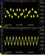
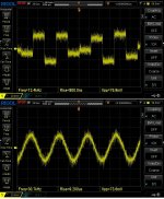
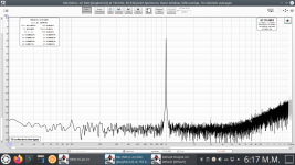
If you want to test for IMD products, don't use a single test tone. Either use a dual test tone and look for the amplitude of the byproducts within the audible band (1st attachment) or a multitone and check for the rising up of the spectrum between the test tones from the idle base line (2nd and 3rd attachments). This is IMO the single most meaningful measurement. (Note: attachments are from another DAC)
)If you want to test for IMD products, don't use a single test tone. Either use a dual test tone and look for the amplitude of the byproducts within the audible band (1st attachment) or a multitone and check for the rising up of the spectrum between the test tones from the idle base line (2nd and 3rd attachments). This is IMO the single most meaningful measurement. (Note: attachments are from another DAC)
Abraxalito provides two small jumpers/bridges in his Dark LED kit, which makes the filter bypassing as easy as it gets.FWIW I'm trying to include a bypass function
Attachments
Last edited:
All noted, thanks! A lot of things to evaluate when the DAC will be ready. It's going to take some time though... Abraxalito has undertaken the design of a custom filter for me. It won't have the active input and output buffers since my DAC is on steroids. Only the Celibidache filter adjusted for the new impedance involved. So, I'll have to design a motherboard to hold this plus some peripheral circuitry.
Fine MG
Please, keep us informed!
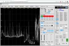
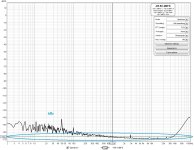
I took some FFTs (2GHz BW) with an SDR dongle and an M sniffer probe. The I2S lines (44.1kHz) pollute up to 1.7GHz !
George
Please, keep us informed!
That was an underestimation.The rise time on the I2S switching waveforms is 1ns to 1.5ns (>200MHz noise spitters).
George
I took some FFTs (2GHz BW) with an SDR dongle and an M sniffer probe. The I2S lines (44.1kHz) pollute up to 1.7GHz !
George
Attachments
-
 6-probe adjacent to the I2S lines .JPG618.9 KB · Views: 109
 -
 5-probe 60mm from the I2s lines.JPG869.9 KB · Views: 111
 -
 4-10mm x10mm M sniffer probe.JPG595.6 KB · Views: 102
 -
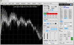 3-spectrum adjuscent to the I2S lines.jpg220 KB · Views: 104
 -
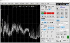 2-spectrum 6cm from the active I2S lines.jpg221.4 KB · Views: 97
 -
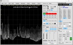 1-spectrum 6cm from the inactive I2S lines.jpg216.5 KB · Views: 108
It's been a few months since receiving Dark I/V, I finally put it into service as the I/V output stage for one of my AD1862 MiroDac's last night.
Wow! Excellent work here Abraxalito, this combo sounds wonderful right out of the box. Besides installing an opamp, this has to be one of the easiest external output stages I've added, really is plug'n'play. No urge to tweak yet....... But, those output caps (C8,C9) might get film bypasses added, hehe.
Current system setup:
MiroDac/Dark IV
Zen Mod Iron Pre (6dB gain)
iTiberius Q17 Amplifier (stef1777 turbo pcb's)
Jim Holtz Finalists
Attachments
Hi! What if the I2S wires are made shorter and untwisted/uncurled? Did you try that already?Fine MG
Please, keep us informed!
That was an underestimation.
I took some FFTs (2GHz BW) with an SDR dongle and an M sniffer probe. The I2S lines (44.1kHz) pollute up to 1.7GHz !
George
- Home
- Vendor's Bazaar
- Dark LED passive filter-I/V stage for NOS DACs