Orders now are open on 'Dark LED' passive filter/IV stage boards, ready built and tested or as a kit for the baseboard with a pre-built and tested filter plug-in. PM me and please don't forget to include your chosen payment method and location so I can quote you inclusive of fees and shipping.
'Dark LED' combines a grounded base (discrete) cascoded stage followed by a 9th order LC filter, then passive I/V followed by a single-ended output buffer, designed to deliver lowest noise. The LC filter does the job of removing DAC images which, when in NOS (no oversampling) begin at 24.1kHz where this filter gives 40dB attenuation. Input sensitivity is +/1mA for 1VRMS out. The grounded base input stage presents a very low impedance to your DAC chip's current output (typically of the order of 5ohm) which helps it give of its best.
Here is how an 18kHz sinewave looks on a typical very-lightly filtered NOS DAC, compared to the filtered output of 'Dark LED' reproducing the same signal :


Preferred payment method is via Wise which typically adds a 2% fee. Our receiving currency is CNY, alternatively USD or Euro. PayPal may also be used, in USD but will attract higher fees, 5.5%.
Price for a Dark LED built and tested unit including top-mounted filter board : 920RMB (~USD128)
A kit with most SMD parts pre-soldered at JLC, filter plug-in pre-built : 720RMB (~USD100)
Physical dimensions: 72mm * 65mm, max height 25mm. Fixing centres : 60mm * 60mm, M3 holes.
Shipping is in addition and depends on your location and speed of service. Courier (FedEx, TNT, DHL) typically takes 8 - 10 days and e-packet four to eight weeks. Not all locations can be serviced by e-packet though.
FAQs
What else is needed to turn the built up Dark LED filter-I/V stage into a fully operational DAC?
You'll need, as a foundation, an existing DAC with a current output, +/1mA R2R chip. A few examples of suitable DAC chips are PCM56, PCM61, AD1860, AD1865 and PCM1702, these all have +/-1mA output in Iout mode. Your base could be an existing DAC board where you wish to bypass its on-board I/V (perhaps a socketed opamp) or maybe just a lash-up on perf-board with your R2R chip of choice. If your chosen DAC chip includes an opamp, be sure that this isn't in-circuit and the input to 'Dark LED' is being taken from the Iout pin of the DAC chip. With a socketed single opamp I/V the DAC Iout can usually be taken from pin2 (-ve input) of the socket when the opamp's removed.
Next you'll need a well regulated low noise power supply of dual rail +/-18V rated at 100mA or higher. An LM317 and LM337-based board set to the correct output voltages will be the bare minimum noise-wise. If you already have a single winding AC supply (an AC wall-wart) then 18VAC at 10-20VA would be in the right ballpark. Use a half-wave rectifier so you get both rails from a single winding or alternatively, a centre-tapped trafo. I don't recommend using switching supplies due to issues with common-mode noise, its very hard to filter out.
Third you'll be wanting some output sockets, typically RCAs so you can connect your Dark LED I/V to your amp or preamp. But your existing DAC may already have these, fed from its own filter stage.
What will I have left to solder if buying the kit version?
The parts JLC hasn't soldered are three NP0 capacitors, several 0.1% thin film resistors, ferrite beads (all 0805 size), SOT-89 transistors, 7mm dia inductors and the through-hole parts which are electrolytic caps and connectors.
What, if anything, is unique about Dark LED's design?
The LC filter is hand-built with in-house wound close tolerance gapped ferrite cored inductors, selected NP0 ceramic caps and the rest of the circuitry uses discrete (bipolar and MOS) transistors to deliver as low noise as possible. To this end, an SE (single-ended) approach is taken with I/V. The name 'Dark LED' comes from the use of infra-red LEDs as voltage references, which are very low noise indeed.
The use of IR LEDs helps reduce intrinsic and power-supply coupled noise meaning that a heroic ultra-low noise PSU isn't required, LM317/337 deliver satisfying results sonically at around 20uV audio band noise. Some technical background to the design can be found on my blog : https://www.diyaudio.com/community/threads/i-v-stages-and-noise.391189/post-7146239


'Dark LED' combines a grounded base (discrete) cascoded stage followed by a 9th order LC filter, then passive I/V followed by a single-ended output buffer, designed to deliver lowest noise. The LC filter does the job of removing DAC images which, when in NOS (no oversampling) begin at 24.1kHz where this filter gives 40dB attenuation. Input sensitivity is +/1mA for 1VRMS out. The grounded base input stage presents a very low impedance to your DAC chip's current output (typically of the order of 5ohm) which helps it give of its best.
Here is how an 18kHz sinewave looks on a typical very-lightly filtered NOS DAC, compared to the filtered output of 'Dark LED' reproducing the same signal :
Preferred payment method is via Wise which typically adds a 2% fee. Our receiving currency is CNY, alternatively USD or Euro. PayPal may also be used, in USD but will attract higher fees, 5.5%.
Price for a Dark LED built and tested unit including top-mounted filter board : 920RMB (~USD128)
A kit with most SMD parts pre-soldered at JLC, filter plug-in pre-built : 720RMB (~USD100)
Physical dimensions: 72mm * 65mm, max height 25mm. Fixing centres : 60mm * 60mm, M3 holes.
Shipping is in addition and depends on your location and speed of service. Courier (FedEx, TNT, DHL) typically takes 8 - 10 days and e-packet four to eight weeks. Not all locations can be serviced by e-packet though.
FAQs
What else is needed to turn the built up Dark LED filter-I/V stage into a fully operational DAC?
You'll need, as a foundation, an existing DAC with a current output, +/1mA R2R chip. A few examples of suitable DAC chips are PCM56, PCM61, AD1860, AD1865 and PCM1702, these all have +/-1mA output in Iout mode. Your base could be an existing DAC board where you wish to bypass its on-board I/V (perhaps a socketed opamp) or maybe just a lash-up on perf-board with your R2R chip of choice. If your chosen DAC chip includes an opamp, be sure that this isn't in-circuit and the input to 'Dark LED' is being taken from the Iout pin of the DAC chip. With a socketed single opamp I/V the DAC Iout can usually be taken from pin2 (-ve input) of the socket when the opamp's removed.
Next you'll need a well regulated low noise power supply of dual rail +/-18V rated at 100mA or higher. An LM317 and LM337-based board set to the correct output voltages will be the bare minimum noise-wise. If you already have a single winding AC supply (an AC wall-wart) then 18VAC at 10-20VA would be in the right ballpark. Use a half-wave rectifier so you get both rails from a single winding or alternatively, a centre-tapped trafo. I don't recommend using switching supplies due to issues with common-mode noise, its very hard to filter out.
Third you'll be wanting some output sockets, typically RCAs so you can connect your Dark LED I/V to your amp or preamp. But your existing DAC may already have these, fed from its own filter stage.
What will I have left to solder if buying the kit version?
The parts JLC hasn't soldered are three NP0 capacitors, several 0.1% thin film resistors, ferrite beads (all 0805 size), SOT-89 transistors, 7mm dia inductors and the through-hole parts which are electrolytic caps and connectors.
What, if anything, is unique about Dark LED's design?
The LC filter is hand-built with in-house wound close tolerance gapped ferrite cored inductors, selected NP0 ceramic caps and the rest of the circuitry uses discrete (bipolar and MOS) transistors to deliver as low noise as possible. To this end, an SE (single-ended) approach is taken with I/V. The name 'Dark LED' comes from the use of infra-red LEDs as voltage references, which are very low noise indeed.
The use of IR LEDs helps reduce intrinsic and power-supply coupled noise meaning that a heroic ultra-low noise PSU isn't required, LM317/337 deliver satisfying results sonically at around 20uV audio band noise. Some technical background to the design can be found on my blog : https://www.diyaudio.com/community/threads/i-v-stages-and-noise.391189/post-7146239
Attachments

Last edited:

Me too! Nice work Richard.
Will it work with PCM58 and tda1387? Maybe not paralleled 1387!
What output will it give with 1mA input?
Will it work with PCM58 and tda1387? Maybe not paralleled 1387!
What output will it give with 1mA input?
Last edited:
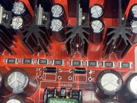
Jim - it will indeed work with TDA1387 for an entry level solution. In fact, I have the PCB for that on my desk as it turned up this morning :

Plain paralleled TDA1387 (more than two I mean) will give out too much current but on this board I plan to try a passive current attenuator to reduce the 8 chips (+/-4mA) here down to +/-1mA. Who knows if it'll sound OK but I figured its worth a try at least.
1mA input gives out 1.5V, so a typical +/-1mA DAC will give out 1VRMS from the I/V stage. Yes it will work with PCM58, that board is already in layout. I'll post a screenshot here when its done.
Dark may be way out of the LED noise issue. Because room light and even light emitted by fellow LEDs in the biasing ckt can mess up biasing. Bread- boarding or prototyping means tradit. biasing LEDs will be affected by ambient, laboratory lighting.
Interesting. Stick some blu tac over them?!
Thanks Richard. I recently got Miro's TDA1541 PCBs fabbed up as I scored a cheap 'A' cd player. See what the fuss is about.! And also one of those tda1387 x8 parallel replacement chips that come in the 28pin . A few comments I've read of folks swapping out 1541 for 1387 piqued my interest. I don't get how the IV works though if they've just swapped out chips in a CD player for example. Reports of 'better' or 'more' bass maybe due to a non linear FR through a sub optimal IV?
OT all this I know sorry .!
I've seen those 'replace TDA1541A' modules on Taobao with the 8*TDA1387. I'm skeptical they can sound as good as TDA1541A because the SNR isn't as good. I am also curious how they get an 8mA output current (from TDA1387s) to replace a 4mA (from TDA1541A). Maybe it just plays 6dB louder?
This is not my cup of tea but I admire the creativity and work that has gone into this. Looks well designed.
I received an early Dark LED I/V and have been listening to it for a few days as the I/V stage for a miro AD1862 DAC. I have one word for it - WOW. In my setup, it sounds better than my previous best, which was using Sparkos opamps for the I/V stage. The instruments are clearer and have more detail. It is very easy to pick out each instrument. It is like a smearing has been removed. The improvement is a whole step better. What came to my mind is the experience I had when I first listened to my Mapleknoll Cleo II air-bearing turntable. Compared to a conventional turntable, I was hearing less background noise and each instrument was clearer and more distinct...kind of jaw dropping. Unfortunately, I no longer have room for a turntable and had to remove it (I guess I should sell it???). I now rely on a good DAC.
Is this the best sounding I/V? I do not know. I only know what I have heard in my system. If you think you might want to try it, I will show what I did to implement this Dark LED I/V.
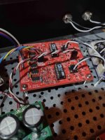
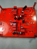
First photo shows the boards just sitting in the enclosure for the evaluation. The next photo shows that I made up another Miro AD1862 DAC pcb so that I would leave my first board intact. Notice there are about half the parts, and I placed the parts on the underside. If you want to add this I/V to your existing DAC, you need to lift the end of the feedback resistors and feedback capacitor (if you have one) that connects to pin 2 of the opamp (the inverting input of the opamp) and remove the opamps, of course.
In the next photo, you can see I put in 8-pin DIP sockets as if opamps would go there. Instead, I soldered the output wires to left over 4-pin sockets (I accidentally ordered several 2X4 sockets just to find out there were 4 pins total!) and plugged the 4 pin sockets into the 8-pin sockets. The I-out wire (white) is plugged into pin 2, and the ground wire (black) is plugged into pin 3. Those wires go to the I-out inputs on the Dark LED I/V board.
The next photo shows the I/V board outputs to the RCA jacks and the +/- 18 VDC power inputs from the PS. I also purchased a PS from abraxalito for the +/- 18 VDC because his PS only needed one 18 VAC input. It uses half-wave rectification to output the needed +/- 18 VDC. That way I could use just one transformer, the one miro recommended in post 6025. of his thread. It has two pairs of 12 VAC and two pairs of 9 VAC. I will put the 9 VAC in series to get the 18 VAC. That transformer just arrived and I will replace my present transformer when I drill 20 holes to mount five pcb's. I wish others would use the 10 mm hole spacing of the diyaudio enclosures 🙂
Until then I am using that temporary AC wall wart transformer for the 18 VAC supply. My other PS board is miro's PS1 which supplies the +/- 5 VDC and the +/- 12 VDC to the DAC board and the I2S board (one I ordered from Aliexpress)
Hope this helps.
Is this the best sounding I/V? I do not know. I only know what I have heard in my system. If you think you might want to try it, I will show what I did to implement this Dark LED I/V.
First photo shows the boards just sitting in the enclosure for the evaluation. The next photo shows that I made up another Miro AD1862 DAC pcb so that I would leave my first board intact. Notice there are about half the parts, and I placed the parts on the underside. If you want to add this I/V to your existing DAC, you need to lift the end of the feedback resistors and feedback capacitor (if you have one) that connects to pin 2 of the opamp (the inverting input of the opamp) and remove the opamps, of course.
In the next photo, you can see I put in 8-pin DIP sockets as if opamps would go there. Instead, I soldered the output wires to left over 4-pin sockets (I accidentally ordered several 2X4 sockets just to find out there were 4 pins total!) and plugged the 4 pin sockets into the 8-pin sockets. The I-out wire (white) is plugged into pin 2, and the ground wire (black) is plugged into pin 3. Those wires go to the I-out inputs on the Dark LED I/V board.
The next photo shows the I/V board outputs to the RCA jacks and the +/- 18 VDC power inputs from the PS. I also purchased a PS from abraxalito for the +/- 18 VDC because his PS only needed one 18 VAC input. It uses half-wave rectification to output the needed +/- 18 VDC. That way I could use just one transformer, the one miro recommended in post 6025. of his thread. It has two pairs of 12 VAC and two pairs of 9 VAC. I will put the 9 VAC in series to get the 18 VAC. That transformer just arrived and I will replace my present transformer when I drill 20 holes to mount five pcb's. I wish others would use the 10 mm hole spacing of the diyaudio enclosures 🙂
Until then I am using that temporary AC wall wart transformer for the 18 VAC supply. My other PS board is miro's PS1 which supplies the +/- 5 VDC and the +/- 12 VDC to the DAC board and the I2S board (one I ordered from Aliexpress)
Hope this helps.
Attachments


Wonderful setup Propitious!!
It's always gratifying when the new piece put in the audio chain is an improvement over the piece it replaced, sounds like Dark LED I/V is a keeper!!
Enjoy the Music!

Richard,
I hope you and Wifey are ready to fire up your solder stations!🤣
It's always gratifying when the new piece put in the audio chain is an improvement over the piece it replaced, sounds like Dark LED I/V is a keeper!!
Enjoy the Music!
Richard,
I hope you and Wifey are ready to fire up your solder stations!🤣
Can the passive IV be changed to get a 2V output?'Dark LED' combines a grounded base (discrete) cascoded stage followed by a 9th order LC filter, then passive I/V followed by a single-ended output buffer, designed to deliver lowest noise.
You can get more output by putting more current in. If you go up to 2mA peak you'll in theory get 2VRMS output but I can't vouch for this level being able to be output at all frequencies without running into clipping at the top of the audio band due to the 'ringing up' of the filter. On almost all music you'll be fine as there isn't close to full level at the highest frequencies.
If you change the I/V resistor for a higher value we'll need higher value inductors in the filter as the filter's matched to the I/V load.
If you change the I/V resistor for a higher value we'll need higher value inductors in the filter as the filter's matched to the I/V load.
Since @propitious feedback about the mounting centres we've updated the PCB to be slightly wider, 65mm. Length is the same at 72mm. Fixing hole centres are 6cm * 6cm M3. Information updated in the first post.Sure thing - I got my calipers out and its 61.8mm (same width as Celibidache and DecaDAC) with a length of 72mm. Height to the top of filter is just under 25mm.
Jim - it will indeed work with TDA1387 for an entry level solution. In fact, I have the PCB for that on my desk as it turned up this morning
Here's the assembled board - only 3 TDA1387s are needed to be fitted to drive the I/V stage to maximum output :
Yes it will work with PCM58, that board is already in layout. I'll post a screenshot here when its done.
One yellow wire on this as I messed up the I2S to RJ decoding. To be fixed on the next rev. Either 2 or 4 PCM58s may be fitted.
Hi Richard,
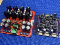
I received my goodies today! The boards look great, very neat and clean soldering. And M3 fastener friendly.
But, will the psu work correctly when a few resistors are not oriented in the same direction??
(🤣 Just Joking)
I received my goodies today! The boards look great, very neat and clean soldering. And M3 fastener friendly.
But, will the psu work correctly when a few resistors are not oriented in the same direction??
(🤣 Just Joking)
Attachments
- Home
- Vendor's Bazaar
- Dark LED passive filter-I/V stage for NOS DACs