Sorry to see you go Martinsson & Circlomanen.
Best of luck with the project and thanks for thinking outside of the box ��
Hope you find a space for supportive conversation and open exchange of ideas.
Dean
Best of luck with the project and thanks for thinking outside of the box ��
Hope you find a space for supportive conversation and open exchange of ideas.
Dean
We have jointly reached the decision to attempt to get a better understanding of what we choose to call TPQWR outside of this thread, and forum, for a while.
The heavy focus on theory, simulations and other ways of accomplishing a similar result instead of trying to see the potential of the TPQWR and what it might be able to contribute with beyond that realm created an atmosphere not in line with the collaboration and support we would have liked to experience at this stage.
Respectfully // Martinsson & Circlomanen
I regret that you guys want to discus/understand the TPQWR theory and concept outside of the forum or even it's own thread. I was highly intrigued by the concept and thoughts of this particular design. But I also understand the why.
I hope someday you both will enlighten us with some insights... 😉
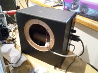
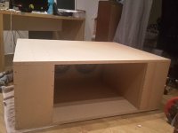
My oldest son has been nagging me for this horn for some time now...
He is going to be using this beast as a computer sound system for games and movies.
😀
Guten Tög, (or however you say "good day") Circlomanen!
Nice to see you back!
That sub probably could shake a hard drive off it's rockers, hope his computer is solid state 😀 .
Art
That sub probably could shake a hard drive off it's rockers
With a single channel from my old H&K surround-receiver (100 watts) everything shakes so violently that all the computer-screens in their large room starts to flicker badly.
There is already cracks between the plasterboards where the putty has crumbled to dust.
😀
My son is happy!!!
Circlomanen,With a single channel from my old H&K surround-receiver (100 watts) everything shakes so violently that all the computer-screens in their large room starts to flicker badly.
There is already cracks between the plasterboards where the putty has crumbled to dust.
😀
My son is happy!!!
Hopefully your son will be happy to repair the crumbling wall boards 😉
Art

When we started to see this kind of cracks all around their walls I quickly removed my bridged QSC RMX1450. Now he uses his small "plateamp" built into his 2.1 Logitech computer speakers. Two TP-QWR loaded Beyma 12P80Nd can play incredible loud and powerful with only those ten watts.

The large TPQWR has about 22 dB higher efficiency the the small 5.25 inch speaker originally in the bass-box. There is no way to balance out the sound. The bass is totally overwhelming and very physically tactile and "large".
Here is the sound of my microphone in my cellphone clipping from the bass:
https://youtu.be/6bkF0J6wOKU
Last edited:
Hi Circlomanen,
That's some pretty radical plasterboard damage in Post #309, looks like the whole board came loose, and moved at the edge. Good decision to cut down the available power. 🙂
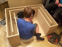
A quick question to the view from inside the box in Post #304, it looks like there is gasket material on the back of the left driver, have you tried to run the box w/ one of the drivers inverted from the other, and if so what did it sound like?
Regards,
I have not tried to mount the driver the other way. There is not enough space behind the baffle for the magnet.
The gasket material is just left in place since the driver was previously mounted in a MTLT box.
I have been drawing a PPSL-TPQWR, as this is an obvious soundquality-upgrade to this kind of tapped pipe construction.
I would like to build a 4-10 PPSL-TPQWR with four Faital Pro 10HP1020. Two plus two in push pull arrangement in the tapped pipe segment feeding into the front quarter wave resonator. I think this would have an enormous potential for both spl and SQ. The Faital Pro 10HP1020 is one of a few uniquely suitable drivers for TPQWR. The B&C 18IPAL also comes to mind, but it is a bit costly.
Cheers,
Johannes
Hi Y'all,
I wonder about Faital Pro's Xmax dimensions, they give their formula, but it sure deviates from the conventional coil height minus gap height divided by two, doesn't it?
Regards,
I wonder about Faital Pro's Xmax dimensions, they give their formula, but it sure deviates from the conventional coil height minus gap height divided by two, doesn't it?
Regards,
Hi Y'all,
I wonder about Faital Pro's Xmax dimensions, they give their formula, but it sure deviates from the conventional coil height minus gap height divided by two, doesn't it?
Regards,
Interesting, with this formula the 18sw115 has an xmax of 10mm, do they exaggerate their values? The bms 18n862 has almost twice that.. I guess that would mean almost twice the amount of air pushed when installed in individually optimized cabinets?
I wonder about Faital Pro's Xmax dimensions, they give their formula, but it sure deviates from the conventional coil height minus gap height divided by two
The real xmax is much more complicated then a very simplified gap-coil-ratio. Very high Bl drivers routinely have a somewhat larger xmax then the simplified mathematic formula indicates. The magnet field does not abruptly end at the exact edge of the pole-piece. With strong modern Nd magnets and well saturated pole-pieces the field will extend a considerable distance outside the gap.
B&C measure their drivers to 10% THD and calls this "xvar". This is a much more interesting piece of data then a simplified mathematical calculation.
B&C Speakers
B&C states the xmax of 12NW100 as 9.0 mm and the measured xvar as 10.0 mm.
Cheers,
Johannes
Thanks for the explanation

PPSL-TPQWR sounds interesting, how deep would a driver with 60 hz resonance frequency be able to go? Is this something similar to the McCauley M421?
Xmax Issues
The Issue of [Xmax] measurement and associated standards are addressed here.
Comments on reaffirmation of AES2-1984 (r1997)
A better measure is Volume displacement [Vd].
Operating a driver well below its [Fs] will take you quicker down a path of already diminishing returns.
If you want to keep the foot print small, and the output clean, use of servo controlled drivers is recommended. Reproducing the first two octaves (8-32 Hz) requires a lot of acoustical muscle.
WHG
In horn and quarter-wave enclosures, the driver resonance is less important. Path length is the dictator of the low corner. No reason you couldn't build a 20hz monster with it.how deep would a driver with 60 hz resonance frequency be able to go?
Often for high efficiency tapped horns, having the driver Fs above the low corner by a bit works well.
"Top-Down" Design
Of course system resonance will be reduced due the additional mass loading provided by a single, very large enclosure containing a 14-foot long column of air.
Alternatively, multiple servo controlled units of much smaller foot-print can be deployed to successfully mitigate room modes, which should be a primary design consideration for a sub system intended to work into a domestic listening space.
WHG
In horn and quarter-wave enclosures, the driver resonance is less important. Path length is the dictator of the low corner. No reason you couldn't build a 20hz monster with it.
Often for high efficiency tapped horns, having the driver Fs above the low corner by a bit works well.
Of course system resonance will be reduced due the additional mass loading provided by a single, very large enclosure containing a 14-foot long column of air.
Alternatively, multiple servo controlled units of much smaller foot-print can be deployed to successfully mitigate room modes, which should be a primary design consideration for a sub system intended to work into a domestic listening space.
WHG
Very high Bl drivers routinely have a somewhat larger xmax then the simplified mathematic formula indicates.
Would have been happy to learn something new, but looking at BCspeaker and studiying data, it doesn't seems to work.
Strong motors (Higher BL or low qes) gives the same variation of deviation from Xvar to Xmax than less powerfull motor.
I simply plotted x= xvar-xmax y= bl or y=qes...for all bc speakers, and for only their 12" range. Can't see relation.
- Home
- Loudspeakers
- Subwoofers
- Danley BC-subs reverse engineered

