I still find the TPQWR more interesting then corresponding TH achieving a similar result, and this is why :
1 / The usable passband of a TPQWR seems to be larger then a corresponding TH when looking at the graphs, this bares closer examination.
2 / The ripple above the intended passband of a TH is rarely useful in my experience and should not be regarded as an extension of the same.
3 / The TPQWR cancels out the unwanted resonances above the passband and creates a gap to the next set of resonances, I could easily regard it as a form of self-filtering design, more so then a corresponding TH.
4 / The passband clearly shows the intended range of use, and within it's passband I see no issue.
5 / The real world Q of a folded TPQWR should make the result much less dramatic then the theory suggests, the set of resonances upwards of the cancellation should have a much lower amplitude then shown in simulation, to my mind even more so then a corresponding TH.
6. The TPQWR is far easier to build the a TH showing a similar response (no angled cuts).
7. The TPQWR is easier to fold into a compact box with regards to unused internal volumes.
8. The TPQWR should therefore be able to achieve a higher volumetric efficiency then a corresponding TH (dB/dm3) within the intended use of range (passband), but this remains to be tested.
I would therefore say that the real world applications for the TPQWR design principle should be very appealing for DIY'ers outside the realm of hornresp.
And no, no matter what you say I can not bring myself to regard this as a stepped TH 🙂 to my mind it sure seems a lot more like a Tapped Pipe (constant area) with a Quarter Wave Resonator on the end of it, therefore I refer to it as a TPQWR, but that is of lesser importance.
These are my thoughts on why this is an interesting principle.
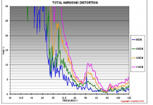
Johannes,1)First of all I am not writing about domestic "wife and kids asleep - easy late night listening to Diana Krall" here. Once you start to push the power levels to a large fraction of the drivers rated power and a large portion of the xmax - then you start to see "Distortion increases roughly by the square of the diaphragm displacement".
Please see the measurements in the graph above.
2)I don´t have any measurements. It is only a logical conclusion that a deep dip in the response will not transmit distortion within that frequency range, while a peak or at least a level spl-respons will transmit harmonics that fall within that range. I have no way to measure that effect though.
1) I could care less about distortion at low levels, the distortion measurements I previously posted were at the drivers full rated power, which results in displacements around Xmax at frequencies above and below Fb. As you should be able to see looking at the displacement compared to test frequencies, displacement does not correlate directly to distortion. Cone breakup modes, bending, etc. all contribute to a complex distortion response.
The graph you posted shows at some frequencies almost no difference in distortion over a 15 dB range. A 10 dB change in level from 95 to 105 would require at least 10 times the power, and more than 3 times the displacement, yet at 31.5 Hz the distortion level only rose from 6% to 17%, less than 3 times the distortion. I see no evidence in the example you chose that shows "Distortion increases roughly by the square of the diaphragm displacement", from what it looks like, if anything it's roughly linear, not logarithmic.
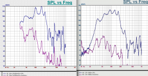
2) You can see in two examples of FLH below that they have steep band pass drops above 200 Hz, yet distortion levels do not fall off as steeply as the frequency dips.
All though you thought a deep dip in the response will not transmit distortion within that frequency range, measurements do not bear out your "logical conclusion".
Other than the rapid increase of distortion caused when a speaker is driven past Xmax, very few generalizations regarding distortion can be made, especially when considering resonant enclosures.
Art
Attachments
Other than the rapid increase of distortion caused when a speaker is driven past Xmax, very few generalizations regarding distortion can be made, especially when considering resonant enclosures.
A more correct statement cannot be made.
Measurements are the only way to know what a driver will do in such an interesting enclosure.
It's also only logical that a 35 db hole in response right beside your passband is going to make it impossible to coherently cross to the mains with good phase and frequency response
During 5 years of building, designing and listening to tapped pipes in a wide variety of venues neither me or my friends have ever experienced a tapped pipe hard to integrate with other speakers, despite a simulated deep depression in the passband.
On the contrary. It does make it easier to itegrate since there is less harmonics that the active crossover can´t remove.
Please build and test a simple tapped pipe tunes to your needs. They are not perfect, but they do have a lot of interesting and useful properties.
Cheers,
Johannes
Johannes.
I'm quite sure that the notch will not be anywhere near as deep as in the simulation.
You can tell that quite easily by using your computer and a function generator program to listen to the sub with a preset sine wave at , just below or just above the place where the notch is predicted.
I use this one:
softsolutions.sedutec.de
it's roughly linear, not logarithmic
increases roughly by the square...
Obviously we agree on "roughly" with regards to distortion in highly resonant enclosures.
😀
Cheers,
Johannes
Most tapped horns have way to much compression.
Like Danley's TH15 and TH18 designs? 🙂
During 5 years of building, designing and listening to tapped pipes in a wide variety of venues neither me or my friends have ever experienced a tapped pipe hard to integrate with other speakers, despite a simulated deep depression in the passband.
On the contrary. It does make it easier to itegrate since there is less harmonics that the active crossover can´t remove.
Please build and test a simple tapped pipe tunes to your needs. They are not perfect, but they do have a lot of interesting and useful properties.
Cheers,
Johannes
If you don't measure anything you don't know how well it integrates. Can you make something that works? Yes. Can it be vastly improved upon? Almost certainly.
I still find the TPQWR more interesting then corresponding TH achieving a similar result, and this is why :
1 / The usable passband of a TPQWR seems to be larger then a corresponding TH when looking at the graphs, this bares closer examination.
2 / The ripple above the intended passband of a TH is rarely useful in my experience and should not be regarded as an extension of the same.
Depends how much of the bandwidth you want to use. A regular tapped horn can have up to 3 octaves of bandwidth, if you don't consider some of that usable you can just cross over lower and get the same amount of passband as shown in this stepped tapped horn.
3 / The TPQWR cancels out the unwanted resonances above the passband and creates a gap to the next set of resonances, I could easily regard it as a form of self-filtering design, more so then a corresponding TH.
Yes, and that hole in response is a problem, not an advantage.
4 / The passband clearly shows the intended range of use, and within it's passband I see no issue.
I don't see a problem in the passband either. The problem is the big gaping hole right beside the passband.
6. The TPQWR is far easier to build the a TH showing a similar response (no angled cuts).
This makes absolutely no difference to me, but if you see it as an advantage you can make most designs stepped, anywhere there's a taper you could step it instead.
7. The TPQWR is easier to fold into a compact box with regards to unused internal volumes.
Only a bit. The tradeoff here is that the sim isn't accurate because the driver isn't at the same space in the physical plan as it is in the sim. If your simulated driver position is at S4 you can't physically put the driver in that spot in the real box, the driver will be forward of S4 by at least 1/2 of it's diameter.
8. The TPQWR should therefore be able to achieve a higher volumetric efficiency then a corresponding TH (dB/dm3) within the intended use of range (passband), but this remains to be tested.
No. Extra space in corners in a tapered design isn't going to make any appreciable difference.
And no, no matter what you say I can not bring myself to regard this as a stepped TH 🙂 to my mind it sure seems a lot more like a Tapped Pipe (constant area) with a Quarter Wave Resonator on the end of it, therefore I refer to it as a TPQWR, but that is of lesser importance.
These are my thoughts on why this is an interesting principle.
You can call it whatever you want but the whole thing is a quarter wave resonator that happens to have a step near the end of the line.
Yeah, I looked at the tapped pipes first when tapped alignments were added to HR since it's what the EV Transflex I built was and knowing what 'tophats' did for TLs in general, which basically mass loaded them like a huge vent, it seemed an obvious tweak, so view these as a ML-TTL or ML-TTP.
GM
GM
Please build and test a simple tapped pipe tunes to your needs. They are not perfect, but they do have a lot of interesting and useful properties.
I've built and measured both a TP with a deep notch and a TH with a somewhat deep notch, both just above the passband. I prefer how they sound with the notch addressed, either through stuffing (in the case of the TH), or a precisely-located constriction (in the case of the TH).
Quote:
8. The TPQWR should therefore be able to achieve a higher volumetric efficiency then a corresponding TH (dB/dm3) within the intended use of range (passband), but this remains to be tested.
I beg to differ, in my experience this is a major pain when it comes to translating a hr-sim into a real built tapped horn, in a square box of decent proportions, with carpenter friendly dimensions, the most efficient folding is the one that does not have to deal with angled cuts, this is especially true if the expansion is non constant or inverted at ~1/2 of the path length as in your bow-tie example, you even said so yourself in this comment (or am I misreading you?) :No. Extra space in corners in a tapered design isn't going to make any appreciable difference.
7. The TPQWR is easier to fold into a compact box with regards to unused internal volumes.
The position of the driver will not be true to the sim in real life, this is absolutely true, but the difference you encounter is borderline negligible with regards to the result to my mind, and at best S3 will be located 1/2 the driver diameter before S4 intersects the path, it will only mean that the expansion is somewhat grater then the systems volume plot would have you believe, it is mainly a theoretical issue and a well worth trade of as I see it.Only a bit. The tradeoff here is that the sim isn't accurate because the driver isn't at the same space in the physical plan as it is in the sim. If your simulated driver position is at S4 you can't physically put the driver in that spot in the real box, the driver will be forward of S4 by at least 1/2 of it's diameter.
Last edited:
Hi Circlomanen and martinsson,
Always good to see another wrinkle on the subject of tapped 1/4 wave subs. I would have been great to have this in its own thread as it doesn't seem to have anything to do w/ the Danley BC subs, or am I missing something?
Regards,
Always good to see another wrinkle on the subject of tapped 1/4 wave subs. I would have been great to have this in its own thread as it doesn't seem to have anything to do w/ the Danley BC subs, or am I missing something?
Regards,
I beg to differ, in my experience this is a major pain when it comes to translating a hr-sim into a real built tapped horn, in a square box of decent proportions, with carpenter friendly dimensions, the most efficient folding is the one that does not have to deal with angled cuts, this is especially true if the expansion is non constant or inverted at ~1/2 of the path length as in your bow-tie example, you even said so yourself in this comment (or am I misreading you?) :
The position of the driver will not be true to the sim in real life, this is absolutely true, but the difference you encounter is borderline negligible with regards to the result to my mind, and at best S3 will be located 1/2 the driver diameter before S4 intersects the path, it will only mean that the expansion is somewhat grater then the systems volume plot would have you believe, it is mainly a theoretical issue and a well worth trade of as I see it.
Folding a straight pipe will obviously be faster than folding a tapered pipe, how much faster depends on how proficient you are at folding, how many folds you need to make it fit and how complex the taper is. I have some tricks to make folding pretty quick, easy and hassle free so I don't mind folding tapers at all. Some people don't find folding as simple, and some people don't fold very accurately. Those people definitely would see a huge benefit to folding simple straight pipes.
As far as space efficiency there's not THAT much space in the corners of tapered folds especially if you keep the last bend as far back from the mouth as possible.
I wouldn't call 6 - 9 inches (1/2 diameter of a 12 - 18 inch driver) borderline negligible or a theoretical issue. In a regular tapered TH varying S4 by 6 - 9 inches can cause quite a difference in the sim. I would personally run the sim through Akabak with the proper S4 location just to see what happens. I haven't played around with a stepped design, maybe there's not too much difference in fudging the segment end location points but I still try to be as accurate as possible with the sim if I'm actually going to build something. YMMV I guess.
.......it doesn't seem to have anything to do w/ the Danley BC subs...........
Yeah, as we noted back at the beginning, until more actual data convinces us otherwise, it appears to be a multiple stub FLH terminating on a flat baffle 'wall', which like the BDEAP32 is basically a Bell Labs/WE/Lansing/Altec four driver horn manifold assembly + drivers from the '30s adapted to a truncated point source loaded [mid]bass horn that can be configured into a much larger horn without needing any additional path-length.
GM
Attachments
![[4] driver horn adapter.gif](/community/data/attachments/468/468580-23d1ff95078301b3bf85e8a88b3db702.jpg?hash=I9H_lQeDAb)
Always good to see another wrinkle on the subject of tapped 1/4 wave subs
Thank you tb46! that's an admirable attitude and it is much appreciated.
Personally I think there is a lot of interesting aspects in his approach that extends beyond theory and simulations, as I previously stated in my post on top of page 29, and I sure will continue to look into it.
Hello everyone,
I find very useful and exciting the TPQWR aproach and also interesting but the aproach Danley uses is at least as inreresting as this one and I would love to find out more about it. From what I understand it is a FLH with a tweak at the horn exit where the rest of the enclosure acts as an extension of the horn or as boundary.
Also, how small is the compression chamber of the drivers? From what I see in J1-94 he used a VERY small one . what do you think?
We have jointly reached the decision to attempt to get a better understanding of what we choose to call TPQWR outside of this thread, and forum, for a while.
The heavy focus on theory, simulations and other ways of accomplishing a similar result instead of trying to see the potential of the TPQWR and what it might be able to contribute with beyond that realm created an atmosphere not in line with the collaboration and support we would have liked to experience at this stage.
Respectfully // Martinsson & Circlomanen
The approximate volume of the compression chamber would be fairly easy to determine from DSL's interior view of the JH-90. The JH-90 appears to be a simple short offset one bend FLH peaking around 75 Hz, rolling off at about 18 dB per octave below. The small compression chambers keep excursion in check below Fc.From what I understand it is a FLH with a tweak at the horn exit where the rest of the enclosure acts as an extension of the horn or as boundary.
Also, how small is the compression chamber of the drivers? From what I see in J1-94 he used a VERY small one . what do you think?
The DSL BC (Boundary Coupled) FLH horns also appear to use small compression chambers with longer horn paths terminated with the BC. In the case of the BC218, it can be used as either a BC or standard FLH, frequency response of both configurations are in Post #244.
Attachments

Last edited:
- Home
- Loudspeakers
- Subwoofers
- Danley BC-subs reverse engineered