Very interesting concept! Is this a TH with Resonance Chamber (THRC) or does it need a new name. Can it be tuned to cover a wider frequency range. What is causing the huge dip in the 150-190hz range. +7.5db? wow!
Naming it is up to the guy who made the discovery, and as far as I know that honour falls to Circlomanen, I have not seen anything like this published prior to his post.
As for the principles involved the two segments are non expanding, and can be regarded as two series connected stepped pipe segments, where the first has a tapped function and the second a resonance function, and maybe even a mass loading component to it.
Some suggestions :
TPQW?
TPQWR?
ML TPQWR?
The mystical magical Umma Gumma box... I better leave this to Circlomanen 🙂
Naming it is up to the guy who made the discovery, and as far as I know that honour falls to Circlomanen, I have not seen anything like this published prior to his post.
As for the principles involved the two segments are non expanding, and can be regarded as two series connected stepped pipe segments, where the first has a tapped function and the second a resonance function, and maybe even a mass loading component to it.
Some suggestions :
TPQW?
TPQWR?
ML TPQWR?
The mystical magical Umma Gumma box... I better leave this to Circlomanen 🙂
It's a tapped horn using stepped segments instead of a taper. Nothing new here and you can get pretty much identical response by using a regular taper instead. I showed all of this in this thread a few months ago I believe.
Here it is, post 75 - 79. I duplicated the frequency response of his stepped tapped horn with a tapered tapped horn, a bowtie shaped tapped horn and a front loaded horn. http://www.diyaudio.com/forums/subw...bc-subs-reverse-engineered-8.html#post4102882
There's nothing new or particularly special or nrew about the frequency response shape or the tapped horn shape presented here.
It's a tapped horn using stepped segments instead of a taper. Nothing new here and you can get pretty much identical response by using a regular taper instead.
Well, theoretically what you say is true. If you ignore things like unrealistically high compression that would render the horn useless outside of Hornresp - then yes, you can get the same spl-respons.
The idea here is to avoid extreme compression and create a useable horn that behaves increasingly good at very high spl. With 100 cm2 S2 for a 12 inch driver you would need speaker-cones made of quarter inch steel to withstand the pressure, and the turbulence created by the extreme speed of the airflow inside the ducts would make the horn into an modulated air-raid siren, not a bass horn.
A regular taper does not have the same mass-loading property as a straight non expanding section.
An externally hosted image should be here but it was not working when we last tested it.
Here I have made the last section one straight expanding conical section with the same mouth size and the same total length.
To call this a simple "tapped horn with stepped segments" is a oversimplification. It is like calling a piece of spruce bark and a crude oil supertanker "boat". Sure... Both of them floats in water.
It can be an open baffle - since there is no actual box encapsulating the driver, or a bassreflex box with a very small cross-section of the "box" and a huge offset port. It all depends on how much you ignore the details that differentiates the different types of enclosures.
Johannes.
You have shown several other ways of accomplishing a similar response using other design principles, true, but there are as I see it a couple of significant differences.There's nothing new or particularly special or nrew about the frequency response shape or the tapped horn shape presented here.
Tapped pipe designs offer more in terms of passband and tuning compared to a TH of similar external volume trading some of their sensitivity in the process, but by coupling a tapped pipe to a QWP resonator you then gain back a lot of that sensitivity over a large part of the TP's passband and lifting the centre dip in the process if balanced properly, all this without adding restrictions in the segments, keeping the working conditions decent for the driver, add to that yet another benefit that will become apparent when it comes to translating the simulations into some form of easy to build folding schematic.
It is not a tapped horn unless you approximate it down to only two states to describe it in total and disregard the fact that there are no steps or expansions prior to the second driver tap, nor is it after, it is to my mind a tapped pipe, constant area, with a series coupled resonator chamber also with constant area, both with mass loading properties.
Is this a point of view? maybe, regardless of which I have not seen any design of this kind put forward/published prior to this one, that makes it new, or a new mix of existing principles providing an impressive end result.
Johannes,To call this a simple "tapped horn with stepped segments" is a oversimplification. .. It all depends on how much you ignore the details that differentiates the different types of enclosures.
One thing for certain, your design shares a lot more in common with a tapped horn than a BC horn, which is a FLH with a mouth restriction and a large baffle, kind of the polar opposite of your design topology.
Whatever you decide to call it, the sims look good, have you done any actual measurements yet?
Art
Well, theoretically what you say is true. If you ignore things like unrealistically high compression that would render the horn useless outside of Hornresp - then yes, you can get the same spl-respons.
The idea here is to avoid extreme compression and create a useable horn that behaves increasingly good at very high spl. With 100 cm2 S2 for a 12 inch driver you would need speaker-cones made of quarter inch steel to withstand the pressure, and the turbulence created by the extreme speed of the airflow inside the ducts would make the horn into an modulated air-raid siren, not a bass horn.
A regular taper does not have the same mass-loading property as a straight non expanding section.
Here I have made the last section one straight expanding conical section with the same mouth size and the same total length.
To call this a simple "tapped horn with stepped segments" is a oversimplification. It is like calling a piece of spruce bark and a crude oil supertanker "boat". Sure... Both of them floats in water.
It can be an open baffle - since there is no actual box encapsulating the driver, or a bassreflex box with a very small cross-section of the "box" and a huge offset port. It all depends on how much you ignore the details that differentiates the different types of enclosures.
Johannes.
You have shown several other ways of accomplishing a similar response using other design principles, true, but there are as I see it a couple of significant differences.
Tapped pipe designs offer more in terms of passband and tuning compared to a TH of similar external volume trading some of their sensitivity in the process, but by coupling a tapped pipe to a QWP resonator you then gain back a lot of that sensitivity over a large part of the TP's passband and lifting the centre dip in the process if balanced properly, all this without adding restrictions in the segments, keeping the working conditions decent for the driver, add to that yet another benefit that will become apparent when it comes to translating the simulations into some form of easy to build folding schematic.
It is not a tapped horn unless you approximate it down to only two states to describe it in total and disregard the fact that there are no steps or expansions prior to the second driver tap, nor is it after, it is to my mind a tapped pipe, constant area, with a series coupled resonator chamber also with constant area, both with mass loading properties.
Is this a point of view? maybe, regardless of which I have not seen any design of this kind put forward/published prior to this one, that makes it new, or a new mix of existing principles providing an impressive end result.
In post 78 here - http://www.diyaudio.com/forums/subw...bc-subs-reverse-engineered-8.html#post4102948
I showed a tapered tapped horn of roughly the same volume of your design. Frequency response is almost identical except my tapered tapped horn doesn't have the horrible dip at 250 hz that yours has. Excursion is almost identical. There's no tight restriction in this design.
I don't see any advantage at all to your design.
The other two designs I showed did have a pretty tight restriction in the line, and I commented on that at the time. I showed them to show that you can get the same frequency response in a number of different ways with completely different alignments. You were suggesting that your frequency response was something special and only attainable with your stepped design. I showed it's easily attainable with a bunch of different alignments.
I don't see any advantage at all to your design.
Personally I think it's to early to tell and would like to know more about it.
I showed a tapered tapped horn of roughly the same volume of your design. Frequency response is almost identical except my tapered tapped horn doesn't have the horrible dip at 250 hz that yours has. Excursion is almost identical. There's no tight restriction in this design.
You have shown that similar results can be achieved using other design principles by simulation, which is totally fine, good job, but the fact that you can achieve similar results in simulation by using other design principles takes absolutely nothing away from this as I see it, and I for one would like to see Circlomanens findings taken further, it seems promising, not at least when it comes down to folding a cab around it.
your design shares a lot more in common with a tapped horn than a BC horn
Yes, that is probably true. I did not understand the large "front-chamber" on the BC412/415 and started to ponder what function it could have. That is the reason I came to this design, and the reason I started this thread.
The BC412/415 does not look like a "normal" FLH, and the published phase response does have some strange peculiarity towards the top of the passband, that FLHs does not usually have - but my design always have.
the sims look good, have you done any actual measurements yet?
Thanks! No measurements yet. I don´t have any tools for any advanced measurements so I will have to rely on the correctness of Hornresp and my ears. Regardless of how near I am to the simulated response, I am still very happy with the results I am hearing - and in the end that is all that matters to me.
I am not here to present my "innovation" as the only true way to bass-heaven. I just want to share what I consider to be a novel idea with some maybe not so obvious advantages over "normal" tapped horns.
Cheers,
Johannes
An externally hosted image should be here but it was not working when we last tested it.
The third harmonic of the first peak in diaphragm displacement coincide reasonably well with the deep suck-out above the passband. This will effectively acoustically short-circuit some of the third harmonic distortion from the driver - greatly lowering the total amount of distortion. Distortion increases roughly by the square of the diaphragm displacement.
The same happens with the second harmonic of the next peak in diaphragm displacement as well.
I guess there is a way to maximize this effect, and this is an area of possible development I hope will take place.
Any distortion lowering mechanism is immensely valuable when trying to push real world spl/dm3 ratio (power density) from a design.
This is a very real flaw with classic tapped horns and FLH. They will "amplify" their own distortion products greatly by all that peaky spl-curve ripple that according to Hornresp can be many dB more efficient then the desired passband of the TH. This is (again) not very important for home audio where you seldom drive a couple of 12 inch drivers with 1500 watts for hours at end, but for professional use where any increase in added usable spl means less boxes to buy, transport, rig, service, make room for etc = increased profitability.
3 dB more spl-capacity from a box equals one less box needed.
This quality alone makes this my proposed design extremely interesting for professional use, where profitability is the bottom line. Add the other advantages with an extremely easy to build design with only straight 90 degree cuts, straight rectangular pieces and bracing inside the boxes, low compression for the driver - greatly increasing the service-life of the drivers and at the same time greatly decreasing the risk of device failure in use, and I believe this is a small revolution in horn design.
Sorry for bragging, but I am kind of proud of tying together all these - according to me - very important aspects of a professional design.
Cheers,
Johannes.
Can it be tuned to cover a wider frequency range. What is causing the huge dip in the 150-190hz range.
With a slightly tapered QW-resonator you can get a few Hz wider frequency range with a small reduction of efficiency. This design already have a wider usable passband then any normal expanding tapped horn design.
The huge dip above the passband is a result of the reflexion from the bottom (beginning) of the tapped pipe. I consider this a very important part - a feature, not a defect - of the design. The tapped horn is a bandwidth limited design. Even though you can have some resonant peaks above the passband, you only have to look at phase and groupdelay to see that those peaks are not usable bandwidth.
Some suggestions :
TPQW?
TPQWR?
ML TPQWR?
The mystical magical Umma Gumma box...
STQWP = stepped tapped quarter wave pipe?
I would like to go with the "The mystical magical Umma Gumma box" but somehow I don´t think the name will stick.
A short and boring name would be Tapped Pipe Quarter Wave Resonator = TPQWR. I guess it is just as fun and catchy as any other five letter acronym i can come up with. I lack the imagination to name something like this.
TPQWR seems like the technical best acronym describing the inherent function of the design.
Cheers,
Johannes

The third harmonic of the first peak in diaphragm displacement coincide reasonably well with the deep suck-out above the passband. This will effectively acoustically short-circuit some of the third harmonic distortion from the driver - greatly lowering the total amount of distortion. Distortion increases roughly by the square of the diaphragm displacement.
The same happens with the second harmonic of the next peak in diaphragm displacement as well.
I guess there is a way to maximize this effect, and this is an area of possible development I hope will take place.
Any distortion lowering mechanism is immensely valuable when trying to push real world spl/dm3 ratio (power density) from a design.
This is a very real flaw with classic tapped horns and FLH. They will "amplify" their own distortion products greatly by all that peaky spl-curve ripple that according to Hornresp can be many dB more efficient then the desired passband of the TH.
What you have done is traded a small peak for a huge dip. The first big peak in tapped horns is usually 5 or 10 db at most and you've traded that for a 35 db dip. Sure, a 35 db dip is going to lower distortion in the frequency range of the dip but it's also going to make it impossible to cross over to the mains properly. Right on the edge of your passband you have a dip that's dropping at something like 100 db/oct and you still need to add a low pass filter to that. How are you going to add mains and coherently match that response in frequency and phase? Check the image attached, your design vs mine. The peak you are worried about is only as high as all the other peaks and it's really not a problem. Creating a 35 db hole to drown it out is not necessary.
This is (again) not very important for home audio where you seldom drive a couple of 12 inch drivers with 1500 watts for hours at end, but for professional use where any increase in added usable spl means less boxes to buy, transport, rig, service, make room for etc = increased profitability.
3 dB more spl-capacity from a box equals one less box needed.
This quality alone makes this my proposed design extremely interesting for professional use, where profitability is the bottom line. Add the other advantages with an extremely easy to build design with only straight 90 degree cuts, straight rectangular pieces and bracing inside the boxes, low compression for the driver - greatly increasing the service-life of the drivers and at the same time greatly decreasing the risk of device failure in use, and I believe this is a small revolution in horn design.
Sorry for bragging, but I am kind of proud of tying together all these - according to me - very important aspects of a professional design.
Cheers,
Johannes.
Where is the 3 db extra spl capacity? Again, look at the attached image. My design is the same size (actually 1/11 larger), same sensitivity and same excursion. There's no extra 3 db there. Even if there was, 3 db does not equal another cab, a fully powered second cab is 6 db more.
Compression is not an issue, again see the attached image. i used exactly the same compression ratio you did.
As I mentioned months ago, the huge hole in response right at the edge of your passband is a problem, not an advantage. Making a horn stepped instead of tapered is a decades old concept. The frequency response curve you seem to prefer is not unique, you can achieve it with a variety of different alignments. You have no extra spl capacity that a simple tapped horn of the same size doesn't have.
I wouldn't be so hard on you if you were not claiming a revolution in horn design when there is literally nothing new here and your claimed advantages like the 35 db hole in response are a really bad idea, not an innovation.
At least we have moved on from the wind vortex at the mouth creating a virtual horn segment external to the box craziness.

Johannes,1)Distortion increases roughly by the square of the diaphragm displacement.
2)Any distortion lowering mechanism is immensely valuable when trying to push real world spl/dm3 ratio (power density) from a design.
3)This is a very real flaw with classic tapped horns and FLH. They will "amplify" their own distortion products greatly by all that peaky spl-curve ripple that according to Hornresp can be many dB more efficient then the desired passband of the TH.
4) 3 dB more spl-capacity from a box equals one less box needed.
1) http://www.diyaudio.com/forums/subwoofers/185588-keystone-sub-using-18-15-12-inch-speakers.html
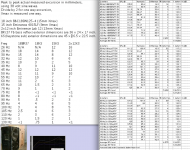
As you can see in the actual measured excursion of a bass reflex cabinet and a tapped horn cabinet with a variety of speakers compared to distortion (post #12), your statement is incorrect. Even in sealed cabinets measurements distortion did not increase at the square of the displacement.
2) Agreed, but the charts below (taken from the above post) indicate the TH generates more distortion for a given displacement than a BR.
3) I have not seen any measurements that corroborate your statement.
4) As JAG already pointed out, another box, speaker and amp adds 6 dB.
Of course, as JAG has mentioned in regards to his "large voice coil" findings, a 3 dB difference between a sim and measured response is "massive" 😉.
Cheers,
Art
Attachments
DISTORTION.JPG Full Screen Image | Audioholics
First of all I am not writing about domestic "wife and kids asleep - easy late night listening to Diana Krall" here. I am constantly referring to high power-levels, so the roughly square relation between power-level and the amount of distortion is not from 0,1 mm to 0,2 mm diaphragm displacement. Once you start to push the power levels to a large fraction of the drivers rated power and a large portion of the xmax - then you start to see "Distortion increases roughly by the square of the diaphragm displacement".
Please see the measurements in the graph above.
This is very dependent on the amount of compression and the suitability of the driver. A TH usually have more spl for any given cone displacement. it is always better to measure distortion based on spl then displacement. If the TH is 5 dB more efficient and produces twice the amount of distortion for a fixed displacement the TH comes out ahead.
Most tapped horns have way to much compression. A S2 (in Hornresp) of less then 50% of Sd is too much compression. JAG used 201 cm2 in his simulation of a tapped horn for the B&C 12NW100. This is 201/550 = 36,5% of Sd. He has still not shown a simulation without very high compression-ratios. Many times this compression is asymmetric due to the expansion of the horn, warping the cone and suspensions. This will increase the distortion-levels very noticeable when you start to push things hard (as in typical pro sound usage).
Cheers,
Johannes
Even in sealed cabinets measurements distortion did not increase at the square of the displacement.
First of all I am not writing about domestic "wife and kids asleep - easy late night listening to Diana Krall" here. I am constantly referring to high power-levels, so the roughly square relation between power-level and the amount of distortion is not from 0,1 mm to 0,2 mm diaphragm displacement. Once you start to push the power levels to a large fraction of the drivers rated power and a large portion of the xmax - then you start to see "Distortion increases roughly by the square of the diaphragm displacement".
Please see the measurements in the graph above.
indicate the TH generates more distortion for a given displacement than a BR
This is very dependent on the amount of compression and the suitability of the driver. A TH usually have more spl for any given cone displacement. it is always better to measure distortion based on spl then displacement. If the TH is 5 dB more efficient and produces twice the amount of distortion for a fixed displacement the TH comes out ahead.
Most tapped horns have way to much compression. A S2 (in Hornresp) of less then 50% of Sd is too much compression. JAG used 201 cm2 in his simulation of a tapped horn for the B&C 12NW100. This is 201/550 = 36,5% of Sd. He has still not shown a simulation without very high compression-ratios. Many times this compression is asymmetric due to the expansion of the horn, warping the cone and suspensions. This will increase the distortion-levels very noticeable when you start to push things hard (as in typical pro sound usage).
Cheers,
Johannes
3) I have not seen any measurements that corroborate your statement.
I don´t have any measurements. It is only a logical conclusion that a deep dip in the response will not transmit distortion within that frequency range, while a peak or at least a level spl-respons will transmit harmonics that fall within that range.
It is easy to hear the effect in real life with a tone-sweep or a tone-generator centered on the frequency of interest. I have no way to measure that effect though.
Cheers,
Johannes
Of course, as JAG has mentioned in regards to his "large voice coil" findings, a 3 dB difference between a sim and measured response is "massive" 😉.
Cheers,
Art
Here's an example. The difference is not more than 3 db anywhere in the curve but the corrected (red) vs uncorrected (blue) sims is massively different, IMO at least. And note that the corrected (red) sim matches the actual measurement much better. Maybe you would not call this massive, but 3 db variation throughout the whole bass region and the very lumpy measured response compared to the uncorrected (blue) sim is cause for concern IMO.
Top - Othorn with Mach 5 UXL as measured by Ricci (data-bass guy)
Bottom - corrected and uncorrected sim (note that while my correction is not perfect it's a whole lot closer to the measurement than uncorrected)
An externally hosted image should be here but it was not working when we last tested it.
Last edited:
JAG used 201 cm2 in his simulation of a tapped horn for the B&C 12NW100. This is 201/550 = 36,5% of Sd. He has still not shown a simulation without very high compression-ratios.
The point of the exercise was to recreate your response curve and displacement curve with a different shape (tapered) and with different alignments.
Please note that I used EXACTLY the same compression ratio that you did in the design I was copying. You chose that compression ratio, not me. If you want to do the exercise again with high compression ratios I can. I'm a bit limited for time but whatever you can do I can match it with a more conventional tapered tapped horn.
I don´t have any measurements. It is only a logical conclusion that a deep dip in the response will not transmit distortion within that frequency range, while a peak or at least a level spl-respons will transmit harmonics that fall within that range.
It is easy to hear the effect in real life with a tone-sweep or a tone-generator centered on the frequency of interest. I have no way to measure that effect though.
Cheers,
Johannes
It's also only logical that a 35 db hole in response right beside your passband is going to make it impossible to coherently cross to the mains with good phase and frequency response.
- Home
- Loudspeakers
- Subwoofers
- Danley BC-subs reverse engineered