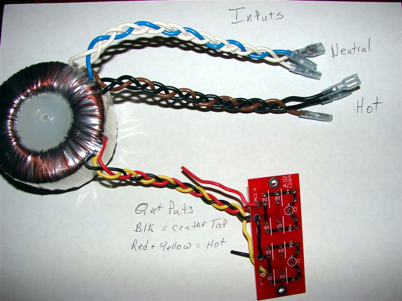
Is it just me or is this pic at Apexjr showing how to hook a center-tapped transformer up to a BrianGT power supply board dangerously wrong?:

(on the page http://www.apexjr.com/miscellaneous.html )
those instructions seem OK until PG+ and PG- are joined together somewhere on the amp board, and then the transformer is being shorted for half the cycle as the output from Yellow to Red is being dropped directly through two of the diodes...
It will seem to 'work', as in the output voltages will seem correct, but the transformer will be buzzing like Hell... until something melts...
No it's fine. It is not the transformer that gets shorted, it's the lower two diodes in the top bridge and upper two diodes in the bottom bridge, thereby making them redundant.
richie00boy said:No it's fine. It is not the transformer that gets shorted, it's the lower two diodes in the top bridge and upper two diodes in the bottom bridge, thereby making them redundant.
Uhhh.... no. You *can* use this board with a center tapped transformer, but *not* the way it's illustrated. Ie, the proper way to do it would eliminate four diodes, jumper the connections into a single bridge, and tie the CT, PG+ and PG- together.
The way it's illustrated in the pic will cause either the transformer to catch on fire, a diode to blow up or the fuse/breaker to blow.
[edit: had an extra BrianGT rectifier board and CT transformer around. Wired it as displayed and sure enough, transformer buzzed, lights on workbench dimmed, then fuse blew when I alligator-clipped PG+ and PG- together. But, multimeter read 60v across +/- as 'expected'.]
Monty
Thank You Dave and Roddy for the heads up...
I've been selling toroids for the Brian Gt's boards and
Troystq ( Troy St Geramain) sent over the picture which
he used to hook up the boards...
Looks like I'll have to take it down...
Anyone else a picture of there hookup's
Steve @ Apex Jr.
I've been selling toroids for the Brian Gt's boards and
Troystq ( Troy St Geramain) sent over the picture which
he used to hook up the boards...
Looks like I'll have to take it down...
Anyone else a picture of there hookup's
Steve @ Apex Jr.
Apex Jr said:Anyone else a picture of there hookup's
Steve @ Apex Jr. [/B]
I can take some. All mine were originally soldered up for dual secondaries tho, and desoldered/modified later for CT transformers, so they may not be the clearest examples because there's solder all over the place 🙂
Monty
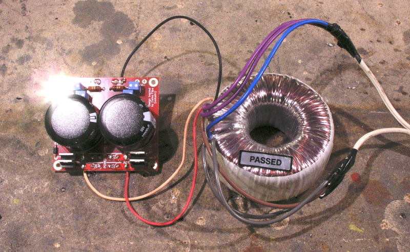
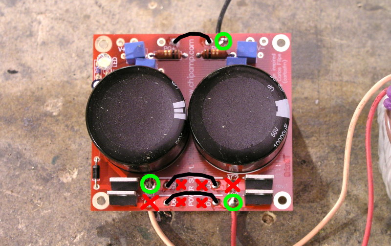
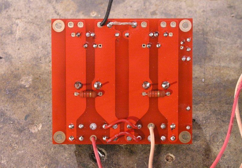
Here are pics of a CT transformer (one of the apexjr 25-0-25 100VA Avel toroids in fact) connected to a new-style snubberized rectifier board, as comes in the current chipamp 3886 kits.
The unused diode pads have solder on them because this board was sitting around assembled for a dual-secondary transformer and I unsoldered the extra diodes and added jumpers to modify it for the center tapped transformer.
Oh, and warm white LEDs are the new blue 🙂


The unused diode pads have solder on them because this board was sitting around assembled for a dual-secondary transformer and I unsoldered the extra diodes and added jumpers to modify it for the center tapped transformer.
Oh, and warm white LEDs are the new blue 🙂


There is also another problem i found with a different power supply floating around on the net and used on BrianGT lm3886-manual pdf
http://www.diyaudioprojects.com/Chip/LM3886_CA/F02-LM3886-power-supply.png
Either the CAP or the Diode bridge must change around, because i can just SEE that electrolytic exploding!!
http://www.diyaudioprojects.com/Chip/LM3886_CA/F02-LM3886-power-supply.png
Either the CAP or the Diode bridge must change around, because i can just SEE that electrolytic exploding!!
xiphmont's pictures are right. For reference, there is a circuit diagram I drew, and some alternative pictures in this thread:
http://www.diyaudio.com/forums/showthread.php?s=&threadid=116512
http://www.diyaudio.com/forums/showthread.php?s=&threadid=116512
Your picture is correct, But in the one in my post the + output of the bridge is connected to the - pin of the 10000uF cap , This is INcorrect.
Or am i overlooking something stupid?
Or am i overlooking something stupid?
The diagram in your post is incorrect, but it seems as though the one up at chipamp.com now is correct.tangmonster said:Your picture is correct, But in the one in my post the + output of the bridge is connected to the - pin of the 10000uF cap , This is INcorrect.
Or am i overlooking something stupid?
xiphmont- I think your method is a better solution and it would be nice of you to make smaller pictures with a how to for Steve's site. I'm sure he would appreciate it.
All-
Steve is a surplus parts seller and I'm sure he doesn't suggest his site as the "reference" for all things electronic.
I (I am in no way affiliated with Steve other than a customer) hooked up his center tapped transformer to a BrianGT board and measured the voltage on the output. It measured appropriately and I hooked it up to an amp. The amp worked and played fine so I emailed him the picture for him to "assist" other hobbiest. Steve most likely has not built one and I know for a fact it worked on my trial amp. I did the test, I took the picture and I emailed it to Steve. Steve is a great supplier and we should do what we can to help people like him stay in business so we can continue to get top quality parts at reduced prices.
If there are errors we are all responsible for calling attention to them and having them corrected.
We are each responsible for our OWN SAFETY.
As you can see below I usually split the center tap for my own amps. I also did a writeup on how to do that with Steve's transformers also.
http://www.diyaudio.com/forums/showthread.php?postid=919294#post919294
troystg said:xiphmont- I think your method is a better solution and it would be nice of you to make smaller pictures with a how to for Steve's site. I'm sure he would appreciate it.
My only worry about smaller pics was that they'd not be clear enough. Probably a diagram would be best.
troystg said:
Steve is a surplus parts seller and I'm sure he doesn't suggest his site as the "reference" for all things electronic.
I (I am in no way affiliated with Steve other than a customer) hooked up his center tapped transformer to a BrianGT board and measured the voltage on the output. It measured appropriately and I hooked it up to an amp. The amp worked and played fine so I emailed him the picture for him to "assist" other hobbiest. Steve most likely has not built one and I know for a fact it worked on my trial amp. I did the test, I took the picture and I emailed it to Steve. Steve is a great supplier and we should do what we can to help people like him stay in business so we can continue to get top quality parts at reduced prices.
If there are errors we are all responsible for calling attention to them and having them corrected.
Agreed-- this was in no way meant to pick on or 'call out' Steve. I've bought multiple transformers from him before and will undoubtedly do so again. He's always been friendly, prompt, and had the right part at the right price. The speed with which he noticed and acted on this thread speaks to the fact that he cares.
The only reason I posted here first rather than mail him directly was because I had the 'surely it must be OK or someone else would have brought it up already' reaction. Hundreds of people from just this site must have seen the picture before I did... I really wasn't sure I wasn't just doing something wrong, missing the way to make it work right...
As for the wrong diagram working.... well it did, sort of. With a 10A fuse, it didn't blow, at least not right away-- things just got real hot with the supply supposedly idling. The output voltages measured properly (the output was being fed by half a cycle with the transformer shorted the other half cycle). The only reason it was obvious something was up was the transformer audibly buzzing (and the bench lights dimming a bit; the supply to the benchtop is only rated at 120v/10A). When I put a 2A fuse on it, it blew pretty quickly.
edit: Oh, and as for splitting the center tap into dual secondaries-- just for informational/archival purposes, it's not clear to me there's any advantage to doing that over just running the board jumpered up for center tapping. If anything, the center tapped version has fewer switching semiconductors generating noise and costing money...
Monty
xiphmont said:......edit: Oh, and as for splitting the center tap into dual secondaries-- just for informational/archival purposes, it's not clear to me there's any advantage to doing that over just running the board jumpered up for center tapping. If anything, the center tapped version has fewer switching semiconductors generating noise and costing money...
Monty ...
Well the whole reason there are dual bridges int there is because some feel it is audibly better. For mine I split the transformers but not ones I build as gifts for friends (7 at last count). All of the friends who have gotten one have been happy with them so far with just a 4 diode BR. 😉
Having searched on the single/dual bridge debate, I see the point of galvanic seperation preventing large charging currents from causing a ground potential to appear between the large caps, as explained by Fred Dieckmann here:
http://www.diyaudio.com/forums/showthread.php?postid=143874#post143874
...but Fred's explanation leaves out the fact that the power supply board and amp in most of the designs are completely seperate, and in a single-bridge configuration are going to be connected by a single power ground cable. The fluctuating 'ground' potential between the two caps (due to wire/plane resistances R1 and R2 in his upper diagram) are going to be limited to the power supply board, because the amp is not going to be fed from two seperate ground lines sprouting from Vcapgnd1 and Vcapgnd2. The power ground, as supplied to the amp, is a single point potential.
And, as this is an unregulated and [relatively] unfiltered supply, the debate is also ignoring the fact that there's plenty of hum on the rails anyway and we're relying heavily on the chipamp's supply noise rejection capability.
What am I missing? (Sorry, I'm not being argumentative, I genuinely want to know).
For that matter, calling them as 2x25 is a bit misleading?
It makes me think there are 2 separate 25V secondaries, while
it's actually a 25-0-25 (center-tapped)?
Any one explain having 6 wires on the primary (2 purple, blue, brown, 2 grey)?
Another Apexjr toroid, which I went for (XFM-D0012) has 2 separate secondaries.
It makes me think there are 2 separate 25V secondaries, while
it's actually a 25-0-25 (center-tapped)?
Any one explain having 6 wires on the primary (2 purple, blue, brown, 2 grey)?
Another Apexjr toroid, which I went for (XFM-D0012) has 2 separate secondaries.
quadtech said:For that matter, calling them as 2x25 is a bit misleading?
It makes me think there are 2 separate 25V secondaries, while
it's actually a 25-0-25 (center-tapped)?
Any one explain having 6 wires on the primary (2 purple, blue, brown, 2 grey)?
Another Apexjr toroid, which I went for (XFM-D0012) has 2 separate secondaries.
He makes it clear it's center-tapped. I don't think that's misleading. I bought twelve last year and knew exactly what I was getting (they're for true monoblocks, so I believe there's no disadvantage to running them center tapped on a single bridge).
AndrewT said:Primary 0-100-110, 0-100-110 maybe?
I wondered that too, but the color coding would almost certainly be different, ne? The leads would not really be interchangable so it would be unlikely they'd be made the same color.
I measured the resistance with a low-ohm tester, and I'm pretty sure the two purples and two greys are just redundant. Maybe it made sense in the context of the amps they were originally made for.
Hi,
If only the blue and brown are connected to the mains supply, what voltages are present on wht-wht, blk-blk and wht,blk?
What voltage between wht-brn & blk-brn?
How can you possibly wire up a transformer if you don't know where the windings connect?
If only the blue and brown are connected to the mains supply, what voltages are present on wht-wht, blk-blk and wht,blk?
What voltage between wht-brn & blk-brn?
How can you possibly wire up a transformer if you don't know where the windings connect?
AndrewT said:Hi,
If only the blue and brown are connected to the mains supply, what voltages are present on wht-wht, blk-blk and wht,blk?
What voltage between wht-brn & blk-brn?
I think you're talking about a different transformer... there is only one black wire (secondary center tap). There is no white.
Oh, you're talking about the pictured toroid, not the one I have, was talking about and showed in my pics, OK....
AndrewT said:How can you possibly wire up a transformer if you don't know where the windings connect? [/B]
I know where the windings connect because I tested it. Perhaps I should have written 'I *had* wondered'. I wonder no longer. That said, the question itself is always a good one to ask yourself 🙂
Monty
xiphmont said:Is it just me or is this pic at Apexjr showing how to hook a center-tapped transformer up to a BrianGT power supply board dangerously wrong?:

(on the page http://www.apexjr.com/miscellaneous.html )
those instructions seem OK until PG+ and PG- are joined together somewhere on the amp board, and then the transformer is being shorted for half the cycle as the output from Yellow to Red is being dropped directly through two of the diodes...
It will seem to 'work', as in the output voltages will seem correct, but the transformer will be buzzing like Hell... until something melts...
OK, I followed the instructions from another thread. You are right.
The output measures fine, but when the chipamp modules are connected, the tranny buzzes like crazy and gets hot within 15 seconds.
Is it worth the effort trying to get this thing to work or should I just get a non CT transformer?
- Status
- Not open for further replies.
- Home
- Amplifiers
- Chip Amps
- Dangerously wrong diagram at apexjr?