Is there a way to hook up a headphone jack to this board directly or would we need to use an output board/buffer board for it?
Is there a way to hook up a headphone jack to this board directly or would we need to use an output board/buffer board for it?
The whole idea for the dam1941 is that it's just the R-2R core and digital interfaces, the things that are hard to do.... So the Power Supply and Output Buffer are separate boards and it's your decision what to use there, and if it will have a headphone amplifier.... There are control signals available on the header for the buffer amp, so you can switch between line out and headphones, just like on a dac1541.
Last edited:
I guess I will have a better idea of what is possible once we find out about the header pin outs. Some are obvious from following the traces on the board. I determined which one is for the I2S input, power, analog out, and controls.
@soekris
Please can you show exactly in the upcoming manual how a Raspberry Pi can be connected to the dam19x1.
TIA
Matt
Please can you show exactly in the upcoming manual how a Raspberry Pi can be connected to the dam19x1.
TIA
Matt
The USB interface sources its power from the USB host.
Is it possible to power the USB interface by the PS which I plan to use for the dam19x1?
This PS is much better than the PS of the USB host.
Thx
Matt
Is it possible to power the USB interface by the PS which I plan to use for the dam19x1?
This PS is much better than the PS of the USB host.
Thx
Matt
You could use a SilentSwitcher which has a a dedicated 6.5/5/3.3 selectable output for the USB interface. Set the ultra low noise outputs to +/-5V and the 6.5/5/3.3 to 5V.
The SilentSwitcher | Linear Audio NL
Then you can supply the whole thing from either a USB charger or a Powerbank for totally mains free, no transformer etc, power.
Jan
You could use a SilentSwitcher which has a a dedicated 6.5/5/3.3 selectable output for the USB interface. Set the ultra low noise outputs to +/-5V and the 6.5/5/3.3 to 5V.
The SilentSwitcher | Linear Audio NL
Then you can supply the whole thing from either a USB charger or a Powerbank for totally mains free, no transformer etc, power.
Jan,
thanks but no solution I am looking for.
@soekris:
Can you give some advice how to solder on the board to get USB power from the PS and not the USB host?
Thx
Matt
Jan,
thanks but no solution I am looking for.
@soekris:
Can you give some advice how to solder on the board to get USB power from the PS and not the USB host?
Thx
Matt
For a type B USB plug, solder to pins:
Pin1 +5V
Pin4 GND
You will want to isolate the 5V from the computer also, be it a specific cable with it already cut or cutting the trace.
IMO, the best would be a jumper on the dam19x1 for supplying the 5V to the USB section of the board either via the power supply of the dam19x1 or via the USB host.
Matt
Matt
Last edited:
J3 header is most likely the I2S header. J3 header could be the jumper or connection point for USB power. We won't know for sure until we see the Users manual or Soren lets us know.
IMO, the best would be a jumper on the dam19x1 for supplying the 5V to the USB section of the board either via the power supply of the dam19x1 or via the USB host.
Matt
That would then break isolation.... The best and only way to power the USB interface is by USB Power from the host.
Or by a separate isolated supply instead of the USB power. You could keep isolation that way. Is that an option?
Or by a separate isolated supply instead of the USB power. You could keep isolation that way. Is that an option?
Not directly, but nothing stops you for adding an external power inserter to the USB interface.
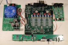
Here is a nice picture of a dam1941 system, with the accessory PCBs mounted.
The Power Supply PCB is only partial mounted, there is room for additional voltage doubled +- supplies for a more demanding Output Buffer.
The basic Output Buffer showed here is using R-R OUT opa1678 opamps, they do fine with just the basic +- 5V, but there are space for DIP sockets for the opamps....
Notice the 3 7-segment LEDs and the encoder for volume, the black part just next is the IR receiver. The User Interface board is designed for a 5mm front plate, but are pretty flexible as except for a few so16 parts it's all leaded parts.
I now have the accessory PCBs in stock, I expect to get the dam1921/dam1941 boards any day now.
Full schematics, drawings and BOMs for the accessory boards will come up tonight on soekris.dk, in the next couple of days full info for the dam1921/dam1941 will come up.
Attachments
Last edited:
Or by a separate isolated supply instead of the USB power. You could keep isolation that way. Is that an option?
This is how I have my current setup however the +5V for the USB is supplied by the AudioZen AZ-lite board. It will be trivial to modify the dam1941 the same way despite no official pin header to disconnect.
I just put up a doc package for the accessory PCBs, both schematics, silk screen drawings and BOMs, on the dam1941 page at Soekris Engineering ApS, Products dam1941
There might be tiny errors, but I will correct them as they're discovered....
There might be tiny errors, but I will correct them as they're discovered....
Last edited:
The User Interface board is designed for a 5mm front plate, but are pretty flexible as except for a few so16 parts it's all leaded parts.
Hi Soren,
is there any chance that you offer the UI board fully assembled and tested?
Would be VERY nice!
Thanks
Matt
- Home
- Vendor's Bazaar
- dam1941 - Next Gen Discrete R-2R Sign Magnitude 24 bit 384 kHz DAC module