Hello Tonno, it looks like that your first suggestion work...I will test it and report...
Thanks a lot...
Thanks a lot...
Can ylu not break down the problem by simply connection a usb input board which you got working prvioisly to see if this is a i2s issue of the 1941 kr if this is a plain linux/PLAYER ISSUE?
Hello,
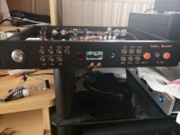
I've been working on my build the last few days. I didn't want the front panel as it is, i don't like the look 😀 So i use a custom one, with custom led and switch.
It is working fine exept the small board with the led matrix and encoder. I use the multicolor flat cable you see on the left corner of the photo. The only mod i do is changing the led matrix for the orange one of the same serie (vishay) to match the build.
When i plug this pcb, the matrix turn on but don't show relevent info (i put -20db in the soekris and the matrix show 0), but if i mouve the encoder the matrix turn off and the dac control go crazy, all led blink, go on/off or change color for the filter led. I don't understand where it come, i check many time the pcb and i don't see any mistake or short circuit.
An idea ?
Regards
Attachments
Hello again,
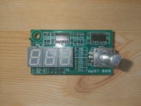
I forget to mention but i use a different encoder : PEC11R-4220F-N0024
It is suppose to be exactly the same but with a different shaft that work better with the knob i choose.
I also attach a photo of the encoder/led pcb. Resistor, cap and connector are on the backside as it allow the pcb to fit my panel.
Regards !
Attachments
Hello again,
I forget to mention but i use a different encoder : PEC11R-4220F-N0024
It is suppose to be exactly the same but with a different shaft that work better with the knob i choose.
I also attach a photo of the encoder/led pcb. Resistor, cap and connector are on the backside as it allow the pcb to fit my panel.
Regards !
Sounds like a basic case of incorrect wiring....
Otherwise your build is nice.
Last edited:
Sounds like a basic case of incorrect wiring....
Otherwise your build is nice.
Indeed but i just don't understand. It couldn't be a bad resistor as their are all the same value, the 3x ceramic caps are good value, the 2 x 74HCT594A are solder in the right side and i don't see any pin badly populate. And for the 2x8 header i just use another flat cable to try without success.
Is the problem could come from the DSP board ? I don't understand how as everything is working fine when i don't connect the led/encoder board.
Is it possible the two 74HCT594A don't like the heat when i populate them ?
Regards
Does the display board work when you plug it directly into the dsp board ?
Make sure that cable is wired so the same pins goes into the right pins as when connected directly.
Does the display board work when you plug it directly into the dsp board ?
Make sure that cable is wired so the same pins goes into the right pins as when connected directly.
I resolve the problem by using simple arduino prototyping cable, so i'm sure it's pin to pin. Pretty stupid problem, i still don't understand how these connector for flat cable are not pin to pin. Anyway, thank you 🙂
May I ask what is the color of your Filter LED when you switch DAC on initially ? Mine is orange, which is a bit strange as this would mean the DAC starts with F5 instead of F4. I would like to understand if F5 is the starting filter or if I have messed up the orientation of the LED when soldering it.
Thx...so I soldered it in the right way and we start with F5 as default...I am now playing with custom filters...any suggestions pn your favourite filters are welcome...
...different topic: has anyone a nice enclosure suggestion ? Hi-Fi 2000 contenitori per l'elettronica, case modding HTPC, Galaxy, rack, DIYaudio, computer cases, front panel express, knobs,milled Handles, milled fronts, hi-end, ?
...different topic: has anyone a nice enclosure suggestion ? Hi-Fi 2000 contenitori per l'elettronica, case modding HTPC, Galaxy, rack, DIYaudio, computer cases, front panel express, knobs,milled Handles, milled fronts, hi-end, ?
Last edited:
I am listening to this currently from the latest 1021.zip filter pack from the filter brewing thread...yes, very good, will test this further, but could become my favourite as well...
Thx...so I soldered it in the right way and we start with F5 as default...I am now playing with custom filters...any suggestions pn your favourite filters are welcome...
...different topic: has anyone a nice enclosure suggestion ? Hi-Fi 2000 contenitori per l'elettronica, case modding HTPC, Galaxy, rack, DIYaudio, computer cases, front panel express, knobs,milled Handles, milled fronts, hi-end, ?
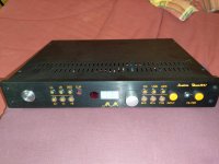
I use one from the galaxy line.
Attachments
![IMG_20190222_214812[1].jpg](/community/data/attachments/679/679465-124b74dc716aad1a5d13a34d64bdc3d0.jpg?hash=Ekt03HFqrR)
In my build i use a galaxy gx343, it's 40mm because i use a ac-dc switch power (5v) with the silent switcher, so i don't need much height.
If someone want my fpd file, i would be happy to give them.
Before the 1941 i got 2x 10²¹ (0.05% version) in bal mode. The update is worth. One of the "problem" with the 1021, it was said on this forum but i ear it myself, was this impression that the sound stage is in 2d, it hadn't this 3d sensation you get with some dac.
I also own a pcm1704 dac and this 3d sound stage is amazing with it, it sound also very "analog". The clear problem is that it's slow, everything that is fast make this dac unhappy. I have a song with very fast heavy metal battery and it's very flagrant 😀
The 1941 however seems to me to have a better sound stage and detail. It's not extremely different from the 2x10²¹, but still significant.
For the filter i didn't make much compare yet, but when i did with the 2x10²¹, in my system the mixed is the clear winner.
Attachments
- Home
- Vendor's Bazaar
- dam1941 - Next Gen Discrete R-2R Sign Magnitude 24 bit 384 kHz DAC module