Chris Daly said:Dear extreme bocky, and others interested in this
implementation
Here is an adjusted article which The Absolute Sound printed
and this magazine- enjoy the music has kindly put up on the net.
http://www.enjoythemusic.com/magazine/viewpoint/0401/deficienciesofspdif.htm
You can also order the original through Electronics World
by finding the article under CD jitter Bug
http://www.softcopy.co.uk/mag/default.asp?dir=ew&p=fulllist&id=79
The only change is a Maxim - Max 497 as an 75 ohm driver
following the transmission end flip flops then interfacing to
the reception end devices.
Cheers / Chris
Something like this, perhaps?
Attachments
One of my famous audio designer buddies called me the other day. His comments:
"I wouldn't brag that I don't know anything about ground bounce, and then point out the magazine articles that I wrote."
His words, not mine. But it does seem that you missed the point wrt ground bounce.
Jocko
"I wouldn't brag that I don't know anything about ground bounce, and then point out the magazine articles that I wrote."
His words, not mine. But it does seem that you missed the point wrt ground bounce.
Jocko
Dear rfbrw
Similar to the transmission end, however reset returns to XRST
CLK is to MCK, the reception end contains three flip flops
as well reclocking the three codes once more. By clocking at
transmission and reception ends it lessens any degradation from jitter arising from the interface, which I consider is beneficial
over the accepted SPDIF standard.
A complete study of jitter would show many other areas where jitter can arise - including the manufacture of the Cd itself. The Stereophile article by Reme Fourre What is jitter published in October of 1993 provides a fairly complete cover of the subject
Sterophile may be able to provide a back issue
Between the transmission end and reception end is a
Maxim Max 497 providing 75 ohm drive.
Cheers /Chris
Dear Jocko Homo
I didnt miss the point, I simply indicated at the word length
speeds and clock speeds the problem of noise on the chips
ground rail is unlikely to arise.
The author raises some fasinating discussion , however
at Cd word length frequencies, and if other decoupling and
good housekeeping is done it is unlikely in this implementation
that ground bounce problems would arise from using AC devices.
The inference i gather from discussion of VCC currents
quickly changing is that as frequency of switching increases
the problem of ground bounce starts. The author from what i have read studied its occurance at 600mhz
AC devices are certainly high bandwith ics that require
every measure of precaution. If you consider this is still a
problem try HC models. I have found no such problem
with 74AC74 ics in this implementation, which is not to say
that ground bounce is not a problem, rather that it is unlikely
to occur at these relatively low frequencies where currents
internal to the ic -comparitively are slow switching.
Cheers / Chris
You did miss the point. He talks about IC architecture because the leadframe inductance is too high, the edge rates are too fast, and the di/dt creates ground bounce. Simple as that.
It has nowt to do with what you are sticking in it: it switches to darn fast. There is absolutely no reason to use logic that switches at a rate much greater than the input signal. It will generate tons of EMI. You can bypass it to death....runs coax cables.....whatever......and it will radiate. There is nothing inside of any CD player operating fast enough to justify using a logic family that is not suited to the task.
Anyway.......a bit OT..............there was guy done in Houston that used to make some gizmo called the IsoDrive. Solved mechanical anomalies in the platter rotation, by adding rotating mass. Had the same effect that reducing electrical jitter did.
Cheers!
Jocko
Chris Daly said:
I didnt miss the point, I simply indicated at the word length
speeds and clock speeds the problem of noise on the chips
ground rail is unlikely to arise. Chris
back at Philips I had a colleague who had put a note on his office wall
"assumption is the mother of all f**k ups"
I'll give you some hints
I've meaured groundbounce amplitudes of 1V and more
Depending on the circuitry such circuit rings
the prop delay depends on the effective supply voltage i.e. groundbounce subtracted
Prop delay modulation is (just one) cause of jitter
does this sound unlikely ?
cheers
Yes but at what frequency ? does ground bounce arise ?
It would appear higher switching speeds cause the
current draw which then exacerbates the problem of
ground bounce. If frequency is kept relatively low surely
the AC gate is then not drawing excessive current
to onset the occurance of ground bounce.
Or is it plagued by this problem regardless of
frequency. if so the description previously quoted
would appear to need correction, and assessment
of how the problem actually arises.
"Ground bounce, which is nothing more than noise on a chip's internal ground rail, mostly involves how quickly you change the current flowing through the chip's ground connections. Noise on the internal VCC rails within a chip involves how quickly the VCC currents change. Slowing the rate of change of either current reduces the noise on the affected internal power or ground rail".
Cheers / Chris
Chris Daly said:Yes but at what frequency ? does ground bounce arise ?
It would appear higher switching speeds cause the
current draw which then exacerbates the problem of
ground bounce. If frequency is kept relatively low surely
the AC gate is then not drawing excessive current
to onset the occurance of ground bounce.
Or is it plagued by this problem regardless of
frequency. if so the description previously quoted
would appear to need correction, and assessment
of how the problem actually arises.
"Ground bounce, which is nothing more than noise on a chip's internal ground rail, mostly involves how quickly you change the current flowing through the chip's ground connections. Noise on the internal VCC rails within a chip involves how quickly the VCC currents change. Slowing the rate of change of either current reduces the noise on the affected internal power or ground rail".
Cheers / Chris
Chris
The bounce is at relative high freqs, depending on the architecture of the chip, but easilly affect the output jitter as the groundbounce voltage is effectively in series with all I/O (and the voltage also differs among the area of the chip).
It cannot be controlled externally, and lowering the clock speed does not help as the on-silicon spedd is fully defined by the transistor properties of which the chip is made of.
Besides that, AC logic has more cross current, also yielding higher groundbounce.
It is just too fast for most digital applications discussed here, that is what Jocko is trying to point out.
Soundwise it is quite easy to hear that HC logic does a better job
In some cases even HCU can be used
Even within HC logic family, performance between various manufacturers differs (a lot), similar as with electron tubes.
No I won't whisper in your ear which is my favourite flipflop supplier......
Hm, originally I wanted to contribute like simply supporting the point of view of Jocko, Guido et al.
But, now I'm a bit confused, and I would like to share with You this state of mind of mine..🙂
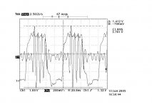
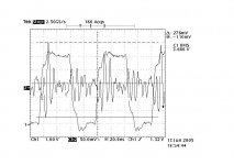
Times ago I had made up a little jig to measure supply rail noise from different cmos gates. It consists of a cmos inverter based 12 MHz clock generator, which is driving a D Flip-Flop tied up like a divider. The divided down signal leaves the bord across a BNC connector fit in, the PS rail signals I am picking off by the means of a TEK P6137; 10.8 pF, 10Mohm, 400 MHz scope probe. With Loong lead lenght.. , though wrapped up as tight as possible.
The 7474 flop is put in a socket, so as to be interchangeable. The local decoupling consists of a 100 uF + 100 nF axial lead kemet ceramic cap, accross pin 7 - pin14 of the socket. No ground plane. The supply is a lab supply with long leads.
Yes, it is a brutal setup, on purpose. I wanted to see the problems better! I know, that the scope probe on pin14 does not pick up power supply voltage bounces only, but rather picks up all the EMI generated
by the circuit. But, I have to note, that this setup produces quite similar signals to which I can see while poking around in a dac or CD player..
The scope is a TEK TDS 654C; 500 MHz - 5 Gs/sec.
Channnel 1 is always the Q output of the flop, connected to the board accross the BNC. Channel 2 is the signal between pin 7 - 14, picked up by the scope probe.
The first diag. is an AC74, the channel 2 input on the scope is non terminated, 1Mohm. [the cable is a 4nsec lemo cable]
Look out for the cursor readings!
But, now I'm a bit confused, and I would like to share with You this state of mind of mine..🙂
Times ago I had made up a little jig to measure supply rail noise from different cmos gates. It consists of a cmos inverter based 12 MHz clock generator, which is driving a D Flip-Flop tied up like a divider. The divided down signal leaves the bord across a BNC connector fit in, the PS rail signals I am picking off by the means of a TEK P6137; 10.8 pF, 10Mohm, 400 MHz scope probe. With Loong lead lenght.. , though wrapped up as tight as possible.
The 7474 flop is put in a socket, so as to be interchangeable. The local decoupling consists of a 100 uF + 100 nF axial lead kemet ceramic cap, accross pin 7 - pin14 of the socket. No ground plane. The supply is a lab supply with long leads.
Yes, it is a brutal setup, on purpose. I wanted to see the problems better! I know, that the scope probe on pin14 does not pick up power supply voltage bounces only, but rather picks up all the EMI generated
by the circuit. But, I have to note, that this setup produces quite similar signals to which I can see while poking around in a dac or CD player..
The scope is a TEK TDS 654C; 500 MHz - 5 Gs/sec.
Channnel 1 is always the Q output of the flop, connected to the board accross the BNC. Channel 2 is the signal between pin 7 - 14, picked up by the scope probe.
The first diag. is an AC74, the channel 2 input on the scope is non terminated, 1Mohm. [the cable is a 4nsec lemo cable]
Look out for the cursor readings!
Attachments
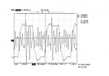
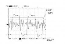
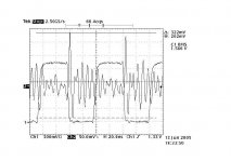
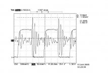

What I noticed from these tests above here, that in the case of termination my test setup is not adequated any more to show the differences. The [probable] EMI disturbances picked up by the scope probe are showing the high current peak where the signal changes states, and then I'm quite sure that the remaining resonances are originated both in the circuit & and the scope probe. In any way, quite the same in all cases.
In the same time, in the non - terminated situation, the pic. is changed strongly - the AC logic behaves like a real noise generator! AND, I should add, that THIS is the case in most of the real life circuits! The short signal path leading to the some kohm / dozen pF input pin of the next logic unit is very far from resistive termination!
Ciao, George
Dear Joseph K,
Very comprehensive !!! , as you point out unterminated lines
cause these overshoots in AC,
However you have found that given proper termination
there is general similarity otherwise in each family of gates.
The AC gate unterminated is a cause of noise generation
however if terminated is similar to other family members.
It would appear the message is to terminate all used and
unused lines when using AC gates.
Many Thanks / Chris
Joseph K said:What I noticed from these tests above here, that in the case of termination my test setup is not adequated any more to show the differences. The [probable] EMI disturbances picked up by the scope probe are showing the high current peak where the signal changes states, and then I'm quite sure that the remaining resonances are originated both in the circuit & and the scope probe. In any way, quite the same in all cases.
In the same time, in the non - terminated situation, the pic. is changed strongly - the AC logic behaves like a real noise generator! AND, I should add, that THIS is the case in most of the real life circuits! The short signal path leading to the some kohm / dozen pF input pin of the next logic unit is very far from resistive termination!
Ciao, George
Hi,
Terminating a 10M-ohm probe is not a wise thing to do.
The source impedance ranges from ohms to some 100's of ohms. They can be meaured using a voltage probe.
Nevertheless the measurements are quite intriguing and the results confirm my conclusions.
I did similar things long a go when I still was at Philips. I made a 10MHz pierce osc using 04 logic, tied input of another inverter to Vcc and meaured the voltage at that output. I used a 450 (!) ohm series termination and 50 ohm load termination at the scope. For the Maxwell lovers among us: A much (50 sq cm) bigger loop was needed to pick up similar induced voltages as measured.
Similarly, faster logic shows higher values of groundbounce. For those knowing what is inside silicon, this all sounds like logic......
Later on, we introduced on-chip decoupling and other measures to reduce the groundbounce.
This is my last post on the subject. Those who want to use AC logic out of some kind of religion are free to do so, others who stick to simple rules like "never use more BW than strictly required" are invited to take over discussion.
back to work now
Questions
Hello all,
George, I am intrigued by your measurements and have a couple of questions:
1. Are you suggesting that the ground bounce problem with AC logic can be fixed with a simple 50 ohm termination on the outputs?
2. Has anyone confirmed that terminating AC logic with 50ohm resistors results in the same SONIC benefit as replacing AC with HC.
FWIW, I replaced the 74AC74 chips on the output stage of my transport (Theta) with HC logic and the sound became more relaxed, less gritty in the highs.
If I can avoid the arduous task of desoldering the AC (the Theta uses doublesided, through hole plated PCB's) and replacing with HC by simply soldering in a 50 ohm resistor with the AC, that would be great!
Thanks for any info,
Ryan
- Status
- Not open for further replies.
- Home
- Source & Line
- Digital Source
- Dac Question - Cs8412 ..... Pcm63