Re: Questions
Hi
Couldn't resist
1) Yes, he suggests that. Termination solves all misunderstood problems, except groundbounce ofcourse.
2) Happy to hear that you prefer HC logic over AC
Desoldering is a nighmare, but you can cut all pins, remove the package and desolder pin by pin. Use a socket for future experiments and make sure the power supply is LOW noise
succes
Dr.H said:Hello all,
George, I am intrigued by your measurements and have a couple of questions:
1. Are you suggesting that the ground bounce problem with AC logic can be fixed with a simple 50 ohm termination on the outputs?
2. Has anyone confirmed that terminating AC logic with 50ohm resistors results in the same SONIC benefit as replacing AC with HC.
FWIW, I replaced the 74AC74 chips on the output stage of my transport (Theta) with HC logic and the sound became more relaxed, less gritty in the highs.
If I can avoid the arduous task of desoldering the AC (the Theta uses doublesided, through hole plated PCB's) and replacing with HC by simply soldering in a 50 ohm resistor with the AC, that would be great!
Thanks for any info,
Ryan
Hi
Couldn't resist
1) Yes, he suggests that. Termination solves all misunderstood problems, except groundbounce ofcourse.
2) Happy to hear that you prefer HC logic over AC
Desoldering is a nighmare, but you can cut all pins, remove the package and desolder pin by pin. Use a socket for future experiments and make sure the power supply is LOW noise
succes
In case anyone hasn't seen this.........
Guido made reference to this article in another post. I do advise reading it.
Goes double if you insist on using logic that is too fast for the application.
http://www.tentlabs.com/Info/Articles/Supply_decoupling.pdf
Jocko
Guido made reference to this article in another post. I do advise reading it.
Goes double if you insist on using logic that is too fast for the application.
http://www.tentlabs.com/Info/Articles/Supply_decoupling.pdf
Jocko
Dear all!
I am terribly sorry - or rather ashamed! [again, given that it has happened already once..]
My only excuses are these phrases:
So, what happened is this: being a not serious person, when I was reaching for the old jig I did go by memory, and supposed that the on-board connector goes for the flop Q out. So I just connected the scope probe to pin 14 to monitor the supply jiggles [being this my main point..], and has taken the diagrams.
Well, that connector in the reality was going to the CLK pin! and terminating that pin really has the miracolous effect of - eliminating the output signal...[by going below threshold], and thus eliminating the switching transients.. Ok, just leaving a small glitch so as to create a greater confusion..
So, if you don't mind, and still have patience for me, I would put up again some repeated tests. By the way, all this inflicts only those tests done "terminated". The others remain fully valid - though channel 1 is not the output, just the clock.
In the previous setup I also was not really happy about the long ground lead of the probe - so now I used a nicer probe with a direct ground lead [P6243 - 1pF/1Mohm/1G]. Notwithstanding, I still would not dare to claim that what I see is purely a power glitch.
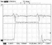
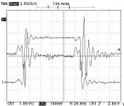
So, here it is: an F74, CH1 is Qout, connected to the scope through a short piece RG174 through LEMO connectors. CH2 is thel scope probe between pin 7 -14, now short leads.
I am terribly sorry - or rather ashamed! [again, given that it has happened already once..]
My only excuses are these phrases:
And also this:But, now I'm a bit confused, and I would like to share with You this state of mind of mine..
Times ago I had made up a little jig..
So, what happened is this: being a not serious person, when I was reaching for the old jig I did go by memory, and supposed that the on-board connector goes for the flop Q out. So I just connected the scope probe to pin 14 to monitor the supply jiggles [being this my main point..], and has taken the diagrams.
Well, that connector in the reality was going to the CLK pin! and terminating that pin really has the miracolous effect of - eliminating the output signal...[by going below threshold], and thus eliminating the switching transients.. Ok, just leaving a small glitch so as to create a greater confusion..
So, if you don't mind, and still have patience for me, I would put up again some repeated tests. By the way, all this inflicts only those tests done "terminated". The others remain fully valid - though channel 1 is not the output, just the clock.
In the previous setup I also was not really happy about the long ground lead of the probe - so now I used a nicer probe with a direct ground lead [P6243 - 1pF/1Mohm/1G]. Notwithstanding, I still would not dare to claim that what I see is purely a power glitch.
So, here it is: an F74, CH1 is Qout, connected to the scope through a short piece RG174 through LEMO connectors. CH2 is thel scope probe between pin 7 -14, now short leads.
Attachments
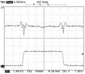
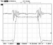
And the same, terminated. These two pic are really a mess, I have tried to position trace 2 [CH2] in the middle, so CH1 extends symmetrically up/down.
What I see here, is the contrary of those previously said [and faithful to good old logic..] The AC logic creates high current glitches at crossing over, which wreaks havoc here with my so-so bypassing structure. [Do not forget, this was my intention] These current spikes are getting worse by the termination..
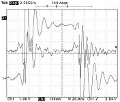
Now, it is definitely possible to use a better bypass setup, and have much less ringing - but, in the same time, look out for the F logic test - much smoother in the same setup. In fact, F logic in a proper bypass situation have shown diminishingly small glitches.
In the future I would like to see also other logic families.
Thanks again, and forgive me!
George
What I see here, is the contrary of those previously said [and faithful to good old logic..] The AC logic creates high current glitches at crossing over, which wreaks havoc here with my so-so bypassing structure. [Do not forget, this was my intention] These current spikes are getting worse by the termination..
Now, it is definitely possible to use a better bypass setup, and have much less ringing - but, in the same time, look out for the F logic test - much smoother in the same setup. In fact, F logic in a proper bypass situation have shown diminishingly small glitches.
In the future I would like to see also other logic families.
Thanks again, and forgive me!
George
Attachments
- Status
- Not open for further replies.
- Home
- Source & Line
- Digital Source
- Dac Question - Cs8412 ..... Pcm63