It's more than made up for by your technical knowledge 🙂Yes, sure, but may be unable to answer all of them (lack some vocabulary ) !!!
Yes that helps, Ciu, thank you - I'll go & read these pagesAbout the transformer, like UTC A-20 :
The given value is a 600/600 if you connect all primaries in series , but this is the impedance , not the DCR : dcr is ~75 Ohms (pure resistive windings)
The inductance L is not (never) given,
Z = L 2Pi x F
When the transfo receives a low frequency, the impedance Z is rather low (how much ? don't know !),the Buffalo gives a lot of current, and with a internal resistance, the voltage goes down, and you feel a lack in low frequencies...
With high frequencies...Z goes upper, the output current is low, ....
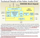
The value of 180 ohms, has an internal impedance of the Buffalo is given, in many places, even in ESS short sheet, the chip ESS9008 is in fact 8 dacs coupled 4 by 4, (4 L & 4 R) each "small-dac" having ~800 Ohms internal impedance .
Have a look on Buffalo posts, page 48 to 50, some idea to run Buffalo in "current mode" with transfos...
Hope this helps ?
R.C.
So this is the 180ohm to 1.5K ratio, I presume? This 180ohm is derived from having 4 paralleled 800ohm DACs per side?The Jensen 10k/10k I choose are about 1.5k primary DCR, so the ratio Source/load is about 9.
Hey Ciu,
Your findings are correct. Any suggestion to run a voltage DAC(Sabre is both) at 600ohm with series resistors is a mistake. I am sure this sounds great.
What you should try though, if you haven´t yet, is to run your Jensen without secondary loading more than your preamp(100k?). Then load the primary with a parallell pure resistive load without series resistors. If you absolutely want filtering you do this on the primary parallell to the loading resistor. This off course is dependant on transformer but most of them like light loads.
Is there a general principle here that the transformer primary DCR should be about 10:1 ratio to the DAC's internal impedance? (I'm trying to get a handle on all this transformer stuff!). Is the DCR of transformers usually given in their datasheets?
What does the resistor across the primary do?
I also read that putting a load on the secondary deadens the sound.
I have two transformers I'm experimenting with
- a Dave Slagle nickel core 10K:10k with dual primaries DCR 200ohm each so 400ohm end to end
- a Sescom MI-97 600:600 - don't know the DCR will have to measure it.
I'm currently using 2 different Vout DACs:
- PCM1793 which wants to run into a minimum impedance of 1.8K
- a ES9022 Sabre 2 channel Vout DAC which wants a 5K load AFAICT.
Both sound great with the transformers but I wanted to optimise them or at least know the parameters to do so. I put a 1.8K R across the primary of the Slagle trafo & it plays louder as a result but I don't know why?
All help to tease this out appreciated
I will be using the 32bit ES9018 Sabre DAC soon & wanted to use transformers on it's output.
Hey Revintage !
Iv' picked ideas from here :
The primary HF filter :
http://www.jensen-transformers.com/as/as093.pdf
Load on secondary :
http://www.jensen-transformers.com/as/as089.pdf
http://www.jensen-transformers.com/datashts/11p1.pdf
About the primary HF filter, (ref as093) the corner frequency (-3dB) , with 249 Ohms and 2.2nf is ~144khz
With my Buff24, I have to add the internal impedance (180 Ohms each side ) with 100Ohms each side, and 3nf , is ~95khz
I had to "deal" with components I had in stock, carbon Allen Bradley resistors, and Silver Mica caps ; may be I should try 2.2nF ?
About the secondary loading and damping filter :
Using the Jensen JT11-P1, all drawings show the same damping filter : 13k, 620pF
About the load, simulated as "RL" : "must be 10k or greater"
My Mc Intosh C24 is an old (~40 years) transistors mode, input impedance is 47k.
Do you think I should load secondary heavier, to come near to equivalent 10k ?
Thanks !
R.C.
Ciu,
Are you going to try Revintage's suggestions (no series R on the primary legs) or have you tried them before?
Are you going to try Revintage's suggestions (no series R on the primary legs) or have you tried them before?
With my Buff24, I have to add the internal impedance (180 Ohms each side ) with 100Ohms each side, and 3nf , is ~95khz
I had to "deal" with components I had in stock, carbon Allen Bradley resistors, and Silver Mica caps ; may be I should try 2.2nF ?
About the secondary loading and damping filter :
Using the Jensen JT11-P1, all drawings show the same damping filter : 13k, 620pF
About the load, simulated as "RL" : "must be 10k or greater"
My Mc Intosh C24 is an old (~40 years) transistors mode, input impedance is 47k.
Do you think I should load secondary heavier, to come near to equivalent 10k ?
Hey again,
As the proposed circuitry is for a typical voltage DAC with close to zero Zout you should dump the sounddegrading(not make) serial resistors and calculate your eventual cap with the 2*180ohm. I would start with only the parallell resistor and then add the cap if necessary. Does the Sabre need additional filtering? And do start with only the load from you Mc. Must admit I haven´t tried the Jensen only Lundahls. It is of course a matter of listening to find out. Start simple and then add.....
Ciu,
Just because its voltage AND current, you don´t need to worry about DCR being to low. At 20Hz your transformer will have a reactance of at least 10kohm, probably a lot higher, with unloaded secondaries.
I have since long got hold of the hard to find datasheet of the 9008. The 9018 should have the same output section. Can mail it if you want, will just have to locate it....
I have planned to find a 9018 with PCB for transformer out. The Buffalo have a lot of sand at the output and a highish price. Any suggestions?
Hey Lars, I do - Acko's board is just what you want - well designed double sided mixed signal HF board with all the options on board for individual power supplies of your choice to all pins - decoupling options of your choice - and the price should be right.
Give him an email - he'll tell you more. That's what I was referring to when I said I'll be using a 9018 soon. I'll be running it into transformers & using 3.3V batteries to power it (With a possible regulator for 1.2 supplies)!
Now can you say what is the function of the parallel R across the primaries & do we aim for a 10:1 trafo DCR to DAC impedance ratio?
Last edited:
Hey Lars, I do - Acko's board is just what you want - well designed double sided mixed signal HF board with all the options on board for individual power supplies of your choice to all pins - decoupling options of your choice - and the price should be right.
Give him an email - he'll tell you more. That's what I was referring to when I said I'll be using a 9018 soon. I'll be running it into transformers & using 3.3V batteries to power it (With a possible regulator for 1.2 supplies)!
Now can you say what is the function of the parallel R across the primaries & do we aim for a 10:1 trafo DCR to DAC impedance ratio?
Will contact Acko.
The parallell resistor is for loading the DAC in voltage mode. Should probably be somewhere between 2k and 10kohm. You don´t need to worry about DCR when using the 9018.
I know it loads the DAC but how does it differ from a series R on each leg & what advantage to using it rather than series R?Will contact Acko.
The parallell resistor is for loading the DAC in voltage mode. Should probably be somewhere between 2k and 10kohm.
Huh? Is it not the 9018 that was being talked about in these Sabre DAC discussions or did I miss something? I know it can do current or voltage mode output - is this why you are saying it doesn't matter? But there must be an optimal or target load for it - in current mode it's 0ohm, I think?You don´t need to worry about DCR when using the 9018.
Hey again,
As the proposed circuitry is for a typical voltage DAC with close to zero Zout you should dump the sounddegrading(not make) serial resistors and calculate your eventual cap with the 2*180ohm. I would start with only the parallell resistor and then add the cap if necessary. Does the Sabre need additional filtering? And do start with only the load from you Mc. Must admit I haven´t tried the Jensen only Lundahls. It is of course a matter of listening to find out. Start simple and then add.....
Yes, you are probably right, but I was so happy with my actual configuration, that I stopped testing and spent my time listening my music , rather than improving each detail...
3nF accross primary gives 145khz -3dB, have to " listen to "
Buff24, is ESS9008, 24b/192khz
Buff32, is ESS9018, 32b/192khz
<OffTopic>
I 'm on a another problem with Buff24 : usb/spdif input thru Valab Teralink ?
</OffTopic
Thanks !
Richard
Last edited:
Hey jkeny,
With the unnecessary series resistors that are there to protect a std voltage DAC from frying and make it possible to filter the zero Zout you also depend on the secondary loading. As you said in a previous post secondary loading could kill sound.
I only think of 9018 as a voltage DAC but as it can take zero ohm you don´t need the 100ohms. As I said one should try between 2k(maybe start a little higher at your proposed 2*160ohm*10) and 10kohm. Only your ears can tell. Of course a frequency plot can show if there is any peaking that should be damped.
I know it loads the DAC but how does it differ from a series R on each leg & what advantage to using it rather than series R?
With the unnecessary series resistors that are there to protect a std voltage DAC from frying and make it possible to filter the zero Zout you also depend on the secondary loading. As you said in a previous post secondary loading could kill sound.
I know it can do current or voltage mode output - is this why you are saying it doesn't matter? But there must be an optimal or target load for it - in current mode it's 0ohm, I think?
I only think of 9018 as a voltage DAC but as it can take zero ohm you don´t need the 100ohms. As I said one should try between 2k(maybe start a little higher at your proposed 2*160ohm*10) and 10kohm. Only your ears can tell. Of course a frequency plot can show if there is any peaking that should be damped.
Any idea to go "current Dac output" using Buffalo24 coupled with transformers ?
http://www.diyaudio.com/forums/twis...dio-ess-sabre-buffalo-dac-28.html#post1632131
R.C.
http://www.diyaudio.com/forums/twis...dio-ess-sabre-buffalo-dac-28.html#post1632131
R.C.
the 9018 is current out at anything under ~700R output impedance. provided it sees less than that it outputs current.
I am very interested in the output of the buffalo dac with transformers 😱
I have found Italian Forum, audiofaidate, which speaks of processors and buffalo dac ..
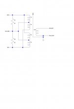
you should use the transformer S & B TX-103 1:10, connected to the current way.
attach file with connection
What do you think of this solution? it is better to insert 1kohm resistor in parallel to the secondary?
I have found Italian Forum, audiofaidate, which speaks of processors and buffalo dac ..
you should use the transformer S & B TX-103 1:10, connected to the current way.
attach file with connection
What do you think of this solution? it is better to insert 1kohm resistor in parallel to the secondary?
Attachments
I have built prototypes of the an ESS DAC with transformer outputs. Works great.
Sorry I can't post schematics because it's a commercial product, but it isn't hard to figure out.
Not sure why you would want to force it into current mode.
Sorry I can't post schematics because it's a commercial product, but it isn't hard to figure out.
Not sure why you would want to force it into current mode.
To Alboran
Why do you need to connect primary-center to Ground ?
It seems you would have an DC offset voltage , someting like Vcc/2 ?
R.C.
Why do you need to connect primary-center to Ground ?
It seems you would have an DC offset voltage , someting like Vcc/2 ?
R.C.
Hello
I do not want to connect ... nothing
I have found this link, and ask your opinion ..
According to you, how to play better ess 9018 +Trasformer ? in a voltage mode or current mode 😕
I do not want to connect ... nothing
I have found this link, and ask your opinion ..
According to you, how to play better ess 9018 +Trasformer ? in a voltage mode or current mode 😕
I think you will do better by removing the resistors, dac ground, and the centertap connections.
all you need is dac+ and dac-
try it.
all you need is dac+ and dac-
try it.
- Status
- Not open for further replies.
- Home
- Source & Line
- Digital Line Level
- DAC ouput using Transformer