I made another experiment. Instead of one battery i tried two with a center tab. They are now parallel to the output caps. Offset is still zero. I did not listen to it but i will.
Maybe someone can make a simulation if that works better.
Maybe someone can make a simulation if that works better.
I made another experiment. Instead of one battery i tried two with a center tab. They are now parallel to the output caps. Offset is still zero. I did not listen to it but i will.
Maybe someone can make a simulation if that works better.
Where is the center tap connect? ground? It's probably fine for a moving coil head amp but maybe not for a DAC I/V converter. I could be wrong though.
No, the signal goes out of the center tab. the batteries are simply in parallel to the 470uF caps in my schematic.
I found one problem with the double battery solution. Both voltages have to be the same or i get an offset.
I found one problem with the double battery solution. Both voltages have to be the same or i get an offset.
Yeah, that makes sense. Batteries aren't guaranteed to have exactly the same voltage.
What do you like to win with the BISS ? I asume less distortion.
In terms of speed we are alraedy at 4.5Mhz and a gain over 30 and noise is really low.
And with a much simplified circuit.
Anyway, i am open to sugestions and look forward to your full steam implementation.
sorry for the long delay.
forget the biss, at this current level maybe the difference in distortion is minimal.
what i propose to you is connect your circuit like the Pass zen and you get rid of the electrolytics in the signal path, use 10uf film capacitors, you can also use batteries.
Other porpose is to connect the collectors of helper transistores to the input like shinja suggested in one post, you will get less harmonic distortion (you can try this with your circuit).
Attachments
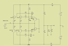
I made another experiment. Instead of one battery i tried two with a center tab. They are now parallel to the output caps. Offset is still zero. I did not listen to it but i will.
Maybe someone can make a simulation if that works better.
If you increase voltage in the input transistors, you will get less distortion.
But at this voltage output levels, the difference is minimal, with voltages like 1 Vrms will make a difference
SMMS73 would it be possible to inject current into the circuit and then take it out again via current-mirrors. Then we could raise gain and avoid caps all together
SMMS73 would it be possible to inject current into the circuit and then take it out again via current-mirrors. Then we could raise gain and avoid caps all together
You can avoid using caps in the signal path with my topology.
I have been busy designing the pcb for my circuit, i have made some alterations at the output, i will talk about that later.
I measured ca. 80mV over the 5.1 Ohm emitter resistors ( i did not have 4.7 Ohm on hand ). That is 0.08 / 5.1 = ca. 16mA.
I have also thought further and your new circuit comes handy. With my floating supply there is the problem that the helper transistors are connected to ground with the bases.
That way they easy pick up hum on the ground line that should be the shield. I tidied up the layout but i could not get the hum away 100%. Other noise like hiss is extremely low though.
That 16mA i measured with a 12V lead battery. I drive the circuit now on 9V because i have to prepare another lead battery for the other channel.
The input connected collectors work. We have now a bit more speed, -3dB is at 4.9Mhz, but we also loose some gain, that is now 27x.
I can not measure input offset reliable any more. It is under 10uV.
I can not measure input offset reliable any more. It is under 10uV.
Another problem solved, i know where the hum came from.... shame on me....again a stupid mistake but i will not tell you...
I put the new circuit in the system and after mucho experimentation the hum is gone.
What a releave ! So it was not the bases connected to ground. This has consequences on the sound, especially in the bass that is now much more robust and tight. That small hum was fogging a bit and took dynamics and resolution. The light on the feat and liquidity is still there but on a much more firm fundament. I will now try the double battery option.
What a releave ! So it was not the bases connected to ground. This has consequences on the sound, especially in the bass that is now much more robust and tight. That small hum was fogging a bit and took dynamics and resolution. The light on the feat and liquidity is still there but on a much more firm fundament. I will now try the double battery option.
- Home
- Source & Line
- Digital Source
- dac I/V convertion with very low distortion