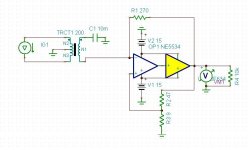
Does post 414 also work with the collectors connected to the input ?
Dirk, i build circuits like that when absolutely the lowest noise is necessary and they work well. The transformers are kind of expensive though.
Dirk, i build circuits like that when absolutely the lowest noise is necessary and they work well. The transformers are kind of expensive though.
Does post 414 also work with the collectors connected to the input ?
Dirk, i build circuits like that when absolutely the lowest noise is necessary and they work well. The transformers are kind of expensive though.
I think one of the advantages is that you can use a cheap transformer and still get good results. I haven't tried it myself.
I think that KSC3503-KSA1381 is promising too.
Yes, the 2SA1407 is much worse in early voltage then the 2SC3601 so this is not such a good match.
I have also measure some ring power transistors from sanken and toshiba, and the curves where even better than the bd140, but it seems a little bit overkill use a TO3P in a MC pré. 🙄
the ksa1381 seems fine. but is something wrong with the curve tracer in the datasheet from fairchild
Does post 414 also work with the collectors connected to the input ?
I don´t see any problem. it should work
Yabba Dabba Do!
very low distortion. Like zip. too many zeros to count.
maybe you are using an ideal transformer. no distortion
maybe you are using an ideal transformer. no distortion
Nope, it is modeled after the Lundahl LL1517. There all kinds of capacitances and winding resistances and core types in the non-linear transformer model I'm using. I've switched to the LME49990 and performance is even better. I'm not going to hijack this thread so I'm not going to talk about this any more. As an amateur, I want certain results, so I will probably build something like this. I don't have a model for the LME49600 buffer, but that's the one I'm going to use (instead of the BUF whatever that's in there). The buffer is required because the feedback network has very low impedance.
So, anyway, back to our regularly scheduled TV programming.... as they say.
What he does is canceling the secondary DC impedance of the transformer. That helps in the bass but not in the treble. That is more complex.
I will now modify my circuit for balanced input.
I got rid of the hum though with other measures using the single ended circuit.
I found though that balanced can sound better.
Common mode distortion should not be much of an issue but common mode noise can be. There is a difference between quiet and dead quiet.
At the moment there is a tiny bit of hum left when i crank it full to un sane levels.
What he does is canceling the secondary DC impedance of the transformer. That helps in the bass but not in the treble. That is more complex.
I will now modify my circuit for balanced input.
I got rid of the hum though with other measures using the single ended circuit.
I found though that balanced can sound better.
Common mode distortion should not be much of an issue but common mode noise can be. There is a difference between quiet and dead quiet.
At the moment there is a tiny bit of hum left when i crank it full to un sane levels.
Well, just to give a little background, one of the reasons balanced lines were invented was to make very low signals immune from the huge local hum field. They were doing skin resistance measurements for EKG's or something so they needed to isolate the signal from the noise. It was also used in the telephone industry to allow signals to travel for miles and miles. Anyway, I think the first example is the one I'm thinking of in regards to phono cartridges. The rest of the signal chain doesn't have to be balanced since the signal is then a lot stronger and the connections are short.
I agree. I made a balanced phono amp, the FPS, for Linear Audio 0.
It is a discrete INA. I worked in the High Tech industry in the 80th and knew circuits like that from brain scanners.
It is a discrete INA. I worked in the High Tech industry in the 80th and knew circuits like that from brain scanners.
I build the circuit post 414. It works. DC offset at input is still under 10uV. Speed is even a bit higher at 5.5MHz, -3dB. Interestingly gain is the same as before so it is not 6dB higher then a usual balanced input. I am not sure though if the output of my generator is floating.
It could be that the earth lines of my generator and scope are connected.
I will find out when i put it in my system.
It could be that the earth lines of my generator and scope are connected.
I will find out when i put it in my system.
When i think about it the 3 Ohm input resistance works like a voltage divider on the 6 Ohm source resistance. That can explain that the gain does not go up. It is a very unusual circuit but very flexible. this is new territory, lets explore it.
I also occurred to me that when this circuit works it is a balanced to unbalanced converter.
That could also simplify the design of a balanced input I/U converter for DA converters.
Common mode performance can be optimized by putting the same phase signal into both inputs and then trim the 3 Ohm resistor. That trimmer can then be substituted with a fixed resistor.
That could also simplify the design of a balanced input I/U converter for DA converters.
Common mode performance can be optimized by putting the same phase signal into both inputs and then trim the 3 Ohm resistor. That trimmer can then be substituted with a fixed resistor.
The value of the trimmer that gives the best cancelation is also the input impedance on the positive side, so indirectly it can be measured.
I also occurred to me that when this circuit works it is a balanced to unbalanced converter.
That could also simplify the design of a balanced input I/U converter for DA converters.
Common mode performance can be optimized by putting the same phase signal into both inputs and then trim the 3 Ohm resistor. That trimmer can then be substituted with a fixed resistor.
Ha, that's clever! good job!
So, I have two designs for an IV converter. One has an input impedance of 3.5 ohms and THD (@1kHz) of 0.00057%. The other has an input impedance of 15 ohms and THD of 0.000058%. For both simulations, I use a current source set to 8mA in parallel with a 2kohm resistor to simulate the output impedance of the PCM1794a. Given that this DAC is designed to work into a virtual ground, would it be better to choose the one with lower input impedance in spite of the 10x higher distortion, or should I go with the one with the lower THD anyway? The noise for both is basically the same. Both have frequency response down to 1Hz at least.
I wish there was a kind of feedback that lowered input impedance. I've heard of feed forward, but I don't know enough about it to say anything.
I wish there was a kind of feedback that lowered input impedance. I've heard of feed forward, but I don't know enough about it to say anything.
Last edited:
I should add that the one with the 3.5 ohm input impedance is made from discrete parts, so that in real life it's likely to be worse (possibly much worse) than in simulation, whereas the one with the 15 ohm input impedance is made from chips that are more likely to be closer to the sim in real life.
(maybe I should have posted this elsewhere?)
(maybe I should have posted this elsewhere?)
I have seen circuits here that have an aditional shunt feedack opamp that can bring the input impedance down even futher.
I do not know if that helps but here is a survey of different methods of I/U conversion :http://www.by-rutgers.nl/IV-converter.html
I do not know if that helps but here is a survey of different methods of I/U conversion :http://www.by-rutgers.nl/IV-converter.html
that's great! thank you!
I read through it quickly. I still like my solution the best (with an input transformer) but I suppose it's possible that the DAC will interact badly with my circuit. Right now, it's unknown, but I'm gathering the test gear I need to actually figure this out. This will take time and money. I do note that he said the IV converter stage should have an input impedance of less than 5 ohms, though the CEN and SEN seem to have higher and work OK. I did order two Lundahl transformers yesterday. One step at a time.
Last edited:
- Home
- Source & Line
- Digital Source
- dac I/V convertion with very low distortion