I understood the "base current" of driver transistor swing due to the current swing of 5k ohm resistor.
I misunderstood again ,sorry.
I misunderstood again ,sorry.
Yes, the circuit i build makes some trouble. I have one or two ideas to try though.
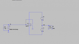
I will publish what i have at the moment. Maybe somebody has an idea how it can be made to work.
Joachim,
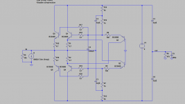
maybe the problem is the dc offset , try connect 2 batteries like this image.
Attachments
I wonder why my build did not work so far. I use different resistors from dirk but it is basically the same. i will do some research soon.
And 1 nanosecond edges will upset operating conditions.
The nonlinearity of bipolars (I do like bipolars, carefully used),
Ie Delta_Vbe
1mA -------
2.718mA +0.026 volt
1/2.718mA -0.026 volt
may show the distortion issue. Boosting Vbe by .026v will almost triple Ie.
Reducing Vbe by .025v reduces Ie by approx 70%.
That is
1mA--baseline bias
2.718mA at +26mv
0.39mA at -26mV
That's a big positive response, versus weak negative response.
Lots of 2nd harmonic.
tank
Hi,
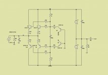
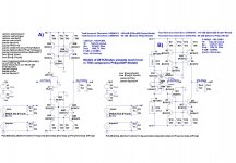
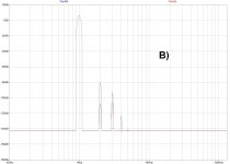
just to show the differences in THD only due to different models:
The circuit simmed is described in #95 and #99 of the Zen-Cen-Sen thread A), B) is a bipolar Version.
The differences in A) and B) are the sole use of either the Philips/NXP models of the BC847C/857C or the BC847BS/857BS of Zetex/Diodes.
For both circuits the differences in THD are remarkably high, with the Zetex/Diodes models giving app. 25dB lower THD!
The spectra of THD remain similar in A), with a clean decay towards higher Ks, but the level of the Ks change. The spectra of B) differs in that K3 is higher than K2. Overall Level of THD is again much lower with Zetex/Diodes Models.
Another Sim of B) using the BC807-40/817-40 Models of Philips/NXP (807/817 are the SMD versions of BC327/337) gave similar, rather slightly worse results to the sims with the BC854C/857C Philips models. No improvement in noise figures also.
jauu
Calvin
Attachments

Last edited:
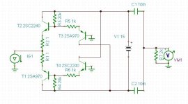
I really like the Bipolar version.. A little paradise in that.. I have experienced that the mirror with only one helper and both connections from the source side has higher and more even impedance. Have you tried the 337-327-40 transistors in that circuit..??
Also it would be possible to inject current via mirrors and servo the circuit so there will be no need for adjustments.. well maybe adjustment for the DAC current off set.
Also it would be possible to inject current via mirrors and servo the circuit so there will be no need for adjustments.. well maybe adjustment for the DAC current off set.
Using discrete/unmatched bipolars, you'll need to have 100 milliVolts DC voltage
across emitter degeneration resistors. Thus at 10mA you'll need 10 ohms.
To tweak that current, inject up to 5mA (thus accomodating up to 50mv Vbe
mismatch) by hanging a high-value resistor to GND (which degrades PSRR).
If you hand-select bipolars for matching, within 10mV, you'll still need
degeneration resistors to assist in balancing the up and down behaviors, and
you'll still need say 10 ohms (and 100mv DC drop), but you can inject less
tweak-current. Using a current-source (cascoded for high Rout) as injector
will preserve PSRR.
Similar (but not identical) bipolar versions as Joachim has built have been discussed and tested at the original CEN IV thread.
Here are a few links, if I may :
http://www.diyaudio.com/forums/digi...on-minimalistic-iv-converter.html#post2694418
http://www.diyaudio.com/forums/digi...minimalistic-iv-converter-10.html#post2793168
http://www.diyaudio.com/forums/digi...minimalistic-iv-converter-10.html#post2789480
We still have a few of those CEN BJT PCBs left that Davide built his with.
You are welcome to those if you would cover postage and packing.
We are definitely sticking to JFET ourselves, despite the high-ish Zin.
Patrick
I am still not able to make this new input stage work. I found a mistake in my voltage divider that i use after my audio oszillator. After fixing it again i got oszillation. I hope i have not destroyed anything but the currents and voltages in the circuit look resonable.
I will now try the other channel.
Things go slow here, it is extremely hot outside so i am more in the mood to digest a cold drink. Tonight i will go to cinema with my son. Prometheus by Ridley Scott.
I will now try the other channel.
Things go slow here, it is extremely hot outside so i am more in the mood to digest a cold drink. Tonight i will go to cinema with my son. Prometheus by Ridley Scott.
Last edited:

shinja is a clever guy 🙂Very very clever. Love it to bits ......
Still not sure if it sounds like opamp ???????????
🙂
Patrick
Use a lme49600 and you will have a killer cen.
shinja is a clever guy 🙂
Use a lme49600 and you will have a killer cen.
HAHAHA. Running an LME49600 backwards! I need a drink.

- Home
- Source & Line
- Digital Source
- dac I/V convertion with very low distortion