...First step: the CD track plaid as it is in its usual transport device, and the DAC set it up for 44,1Khz sampling
Second step: the CD track plaid as it is, and the DAC set it up for 192Khz.
Third step: the CD track extracted, oversampled to 176,4Khz wav 64bit, then converted to FLAC (64bit processing) to an 176,4Khz/24bit file. The file plaid (ASIO 64 bit) with the DAC set it up for 192Khz...
Hi, Coris,
Those appear to be quite interesting subjective results. However, I'm unclear regarding part of your test procedure. Did the "DAC set up" include moving the analog output filter response relative to the DAC's sample rate?
Last edited:
Coris, the way you visualize the differences indicates land-slide differences in imaging. Looks great!! 😎First step: the CD track plaid as it is in its usual transport device, and the DAC set it up for 44,1Khz sampling
Second step: the CD track plaid as it is, and the DAC set it up for 192Khz.
Third step: the CD track extracted, oversampled to 176,4Khz wav 64bit, then converted to FLAC (64bit processing) to an 176,4Khz/24bit file. The file plaid (ASIO 64 bit) with the DAC set it up for 192Khz.
Unfortunately in my testing DAC system I could not access the 176,4Khz sampling step. But anyway, the improvements and the differences are obvious and only impressive, I can say.
Hi, Coris,
Those appear to be quite interesting subjective results. However, I'm unclear regarding part of your test procedure. Did the "DAC set up" include moving the analog output filter response relative to the DAC's sample rate?
Sorry to not answer yet to this question. I was only too lazy to scope something...
Only modified the sample rates, with/without the cap, listen. If should use the scope, then the subjective part of this test, should be reduced quite dramatic...😉🙂
In my case, to do detailed measurements involve enough work, as my DAC system is in prototype phase. I do hope I will putt all together on a PCB in a more professional manner, so, the detailed measurements process should start and being more effective/accurate.
However, the test I have done so, it were enough conclusive for me. I know is not enough to be the same for somebody else, but I have chosen to publish my conclusions, as a step forward in this case...
To be continued... investigated...
Last edited:
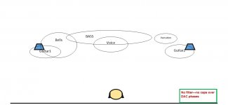
Coris, the way you visualize the differences indicates land-slide differences in imaging. Looks great!! 😎
Is of course "a kind of" visualizing. Difficult to put sounds, and its elements in pictures... Anyway it was my best way I could (for the moment) to show what is happen, using these means. I do hope that it will help so, one can understand that (and almost how) it is happen something in this case... and it will incite others to continue to develop the investigations...
As it may come out from my perceptual illustration, it looks like in the third test the "things" are more in the right place in that sound scene... And actually so it is really (perceptual) happen using this filtering technique.
Last edited:
I feel the need to precise about my last tests, that my DAC setup does not include any other form of filtering, than only this cap (the Rasmunssen Effect).
I suspect Ken referred to an extra filter/filtering in his last post, if I well understood (at last...).
I suspect Ken referred to an extra filter/filtering in his last post, if I well understood (at last...).
I might just mention that that I've played with the upsampling strategy on many occasions over recent times, where a very conventional, but commercial grade, desktop PC with mainboard DAC was fed with different rates of the same original track - and the result was always in favour of the highest rate, essentially the cleanness of the treble always improved.
I've done this to quite "ridiculous" degrees, taking very low bit rate MP3 material, and upsampling that to 24/384 say - the final was so superior, chalk and cheese, as they say ...
Also, upsampling conventional material to ridiculous rates, offline, getting close to the 2.8MHz bitstream levels. And it helps, 🙂. Obviously,this is not the DAC, but the whole PC playback environment interacting, causing subtle quality variations. And useless, because the audio files are now absurdly large - but it proved a point ...
Last edited:
if i make the dual/simmetric topology (with series inductors), can i call it Pergo's effect?
That name will change the real electrical effect?
I'm not talking in enthusiast/audiofool mode 🙂
That name will change the real electrical effect?
I'm not talking in enthusiast/audiofool mode 🙂
Note that we are hypothesizing that the R-effect does not work on NOS dacs. I haven't noticed any sonic differences as yet.
I would be very surprised if this was an effect we would see beyond delta-sigma DACs. But it should of course be confirmed one way or the other. The last thing we want to see is that "I can't see it working" because then you will never actually find out. One should never create a dead end, because it might not be a dead end until you confirm it is a dead end. 😀
UDA1351. In the interests of collectively ensuring we test as many DACs as possible, would this be worth testing for the JR Effect?
UDA1351, took a look at the data-sheet, doesn't say delta-sigma, but look at page 5 and in the block diagram it has a "NOISE SHAPER" and that gives it away that it is d-s.
Yes, I am comfortable in predicting that you will get a result with this DAC, so if you can do it, then do it.
Cheers, Joe
.
I'm not talking in enthusiast/audiofool mode 🙂
Good!
If you want to try Pergo's Effect, then by all means go ahead. A-head and not a big-head, OK? 😉
Cheers, Joe
Last edited:
I might just mention that that I've played with the upsampling strategy on many occasions over recent times, where a very conventional, but commercial grade, desktop PC with mainboard DAC was fed with different rates of the same original track - and the result was always in favour of the highest rate, essentially the cleanness of the treble always improved.
I've done this to quite "ridiculous" degrees, taking very low bit rate MP3 material, and upsampling that to 24/384 say - the final was so superior, chalk and cheese, as they say ...
Also, upsampling conventional material to ridiculous rates, offline, getting close to the 2.8MHz bitstream levels. And it helps, 🙂. Obviously,this is not the DAC, but the whole PC playback environment interacting, causing subtle quality variations. And useless, because the audio files are now absurdly large - but it proved a point ...
There is here about two different things or discussions: one about oversampling/processing the digital files, and another discussion about this filtering effect.
We may not mix these fields...
In my post I have mentioned this digital processing of a file, to accentuate/show the level of increasing in quality (using this filter), when a high quality digital stream (of a higher sampling frequency) is feed it into the DAC system.
I have used the same quality files in my gear before applying this filter (in the same system), and after soldering this cap in place. The difference in quality is important, and have nothing to do with this oversampling of a audio file. It was just something particular in my case, deciding to use a higher quality file, of another sampling frequency to test with.
We can of course talk about digital files processing, but it will be a little bit out of topic, I suppose...
Last edited:
The point I'm making is that most likely the "damage" is being done, or not being done, within the S-D chip. Since it is an electronic part, every lead on that chip is potentionally part of that problem, irrespective of whether it's called an output or an input, a digital or analogue signal, or bias, or voltage supply. I.e. unless every signal going in or coming out wrt the chip is 'perfectly' behaved, and 'perfectly' dealt with, as an electrical entity like the datasheet implies it is, or should be, then it may be part of the answer.
So, think of various sampling data rates being fed to the chip not as digital input - but varying high frequency, analogue interference that the chip has to contend with, in order to work 'perfectly' ...
So, think of various sampling data rates being fed to the chip not as digital input - but varying high frequency, analogue interference that the chip has to contend with, in order to work 'perfectly' ...
Hi, Jesper,
I had wondered the same thing. Does the effect scale with the sampling rate, in which case, it would be convenient to set the filter response targets relative to the Nyquist frequency. Listening for the effect via high sample rate music content would tell for certain.
In anticipation of just this question, I'd previously computed the filter response targets at CD's 22.05KHZ Nyquist frequency, based on Joe's -1.3dB to -1.5db @ 20KHz targets. I got, -1.5dB to -1.6dB @ 22.05KHz, respectively.
Hi Ken,
Thanks for replying ... Actually - hoping that I understood your feedback correctly - my point is that as the sampling frequency gets higher, to my knowledge the higher harmonics of the DAC's output also goes up in frequency. If this capacitor helps reduce out-of-band noise sampling at higher frequencies might make it possible to move up the appr. 20 kHz cut-off frequency with good results. Just a thought ....
And then I noticed that one of you used a Wima FKP-2 capacitor for this ... given the HF content of these signals it might be useful to use the FKP-02 capacitor instead (e.g. available from RS-online). Narrower leads (PCM2.5 instead of PCM5) reduces inductance and thus may make it more efficient in filtering HF.
Cheers,
Jesper
Joe you didn't get the point.
And you didn't get mine?
If you were into loudspeakers, then there is something here that I could tell you about, that is a lot weirder than anything discussed here on this forum or indeed any forum right now: I have constructed a 2nd Order Butterworth Alignment where Qb = 0.707 and this can be driven by any source impedance and still stay a 2nd Order Butterworth Alignment. It also means zero damping factor is required from the amplfier - indeed I can drive it with a "current" amplfifier with an output impdeanhce of 270 Ohm (I made such an amp and published it >>here<<. The method used can also be applied to Crossovers, where no matter what the amplifier used, the Crossover slopes (and hence their Q) will stay locked in.
Of course, I am a liar, or that is what I will likely be told.
But I am getting used to it. It seems to be a common Internet game to call all others liars. A sort of modern form of Pontification. 🙂
Cheers, Joe
.
Last edited:
Of course, I am a liar, or that is what I will be told.
But I am getting used to it. It seems to be a common Internet game to call all others liars. A sort of modern form of Pontification. 🙂
So far I have not seen that happen in this thread.
So far I have not seen that happen in this thread.
I wasn't suggesting that, just aware that it happens.
I just added 'likely' via "Edit' and I was referring to an 'effect' in loudspeakers that is truly weird and if they are skeptical about this, then I can only imagine...? But a group of local speaker designers are working on this here in Sydney and it is mucho bigger deal.
Cheers, Joe
Last edited:
Dude, that Trans-Amp is an old story. Just see in many many threads, indeed in push-pull discrete amps.
Try with real loads and see why it's rarely used 😉
I've read to much audiofool threads. Need some real measures, so you can easy get my point.
I prefer technical instead audiofoolish.
Try with real loads and see why it's rarely used 😉
I've read to much audiofool threads. Need some real measures, so you can easy get my point.
I prefer technical instead audiofoolish.
Dude, that Trans-Amp is an old story.
Huh?
The amp wasn't the point !!!
This thing you have about "audiofoolish" - maybe taking it a little too far?
Not a little condescending...
Michael Faraday felt in his guts that light was electromagnetic waves. He couldn't prove it - and he didn't have the maths. Then a friend called James Maxwell came to his help. Meanwhile Faraday was ridiculed until Maxwell's maths proved Faraday was right.
I ask you, should Faraday have stay silenced? In that case we would not have heard about James Maxwell - and on his wall in his study Einstein had the pictures of Faraday, Maxwell and Newton side by side.
If it was not for Faraday and Maxwell, would Einstein have come up with E=MC^2 ????
So dear Pergo, please moderate your tone.
Last edited:
- Status
- Not open for further replies.
- Home
- Member Areas
- The Lounge
- DAC Filtering - the "Rasmussen Effect"