Hi all,
First ... I'd like to say that I haven't read all of the thread so I may have missed something - but reading what I have read I was thinking that the optimum spot for a cut-off might depend on the sampling frequency ... Whether it's 44.1 kHz or 192 or 384 kHz makes for a quite different spectrum from the DAC and so the higher sampling frequencies might allow for setting the cut-off higher. Have any of you experience with this?
Hope I didn't miss this ;-)
Cheers,
Jesper
Hi all,
First ... I'd like to say that I haven't read all of the thread so I may have missed something - but reading what I have read I was thinking that the optimum spot for a cut-off might depend on the sampling frequency ... Whether it's 44.1 kHz or 192 or 384 kHz makes for a quite different spectrum from the DAC and so the higher sampling frequencies might allow for setting the cut-off higher. Have any of you experience with this?
Hope I didn't miss this ;-)
Cheers,
Jesper
Hi, Jesper,
I had wondered the same thing. Does the effect scale with the sampling rate, in which case, it would be convenient to set the filter response targets relative to the Nyquist frequency. Listening for the effect via high sample rate music content would tell for certain.
In anticipation of just this question, I'd previously computed the filter response targets at CD's 22.05KHZ Nyquist frequency, based on Joe's -1.3dB to -1.5db @ 20KHz targets. I got, -1.5dB to -1.6dB @ 22.05KHz, respectively.
Joe,
Your diagram appears to depict high closed-loop gain (feedback based) inverting op-amps (not necessarily monolithic devices, though). I note that your description describes the circuit as not feedback based. Can you clarify?
No intention to confuse - looking at the wrong end of a stick and not intended as circuit recommendations.
I was simply trying to demonstrate where to put the caps and resistors when dealing with different DACs - use whatever is your favourite circuits, mine were only intended as 'blocks' and not a discussion on topology.
Cheers, Joe
Surely this cannot be misunderstood - yes, it is feedback:
The Virtual Earth is nominally Zero Ohm. So the C needs to be before R. That is all that is demonstrated here.
The Virtual Earth is nominally Zero Ohm. So the C needs to be before R. That is all that is demonstrated here.
Attachments
Last edited:
.....
I can well recognize (out of my own measurements) and confirm almost all of these snap shots you have presented here. I was always and I `m using the last one design you have simulated (Opa1632, no feedback cap, almost the same R value, but the cap on input is 1n - no any other filtering, straight to the final opamp, 3x gain, and RCAs). .....
pretty similar - 806pF per two PCM1704
http://www.diyaudio.com/forums/pass...igh-end-off-topic-thread-185.html#post2782683
Don't over-analyse the right side:
Here we now have High Z state on the Inputs, and the R needs to be before C - pretty obvious.
Just use what you are comfortable with, even tubes, differential circuits, feedback or non feedback.
Here we now have High Z state on the Inputs, and the R needs to be before C - pretty obvious.
Just use what you are comfortable with, even tubes, differential circuits, feedback or non feedback.
Attachments
Last edited:
My "simple" approach for achieving the same result is improving the quality of the mains power, reducing other interference mechanisms, and, most importantly, conditioning the DAC and following circuitry for extended periods. The latter is essential, otherwise the sound is dead as a doornail ... the 'pure' approach is feeding the circuit a full strength 18kHz sine wave on repeat, for an hour or so.
Would be interesting comparing the difference between the "cap solution", and conditioning ...
Would be interesting comparing the difference between the "cap solution", and conditioning ...
The offset current must simple by nulled somewhere.
T
Yes indeed.
Next it will be pointed out I didn't show a power supply?

Terry, are you going to try it(?) - of those who have appeared here (and I expected you to show up), I would like you more than anybody else to try it.
Cheers, Joe
Last edited:
I don't mean to use this term "psychoacoustic" in any negative way. The term psychoacoustic to me means any difference in the analogue output that gives rise to an audible difference in the sound & does not mean it is an "imagined" or "purely psychological effect"
Is OK. I did not taken it as negative. 🙂
I've checked the specs of several DAC's. The max. load specified in the datasheets is several pF's. So the Rasmussen effect appears to find its origin in capacitive "overloading" of the DAC, or do I misunderstand the principle?
It can also mean that the interpretation of the measurements, laid down in the specs is "limited" in scope, and do not represent the capabilities well.
It can also mean that the interpretation of the measurements, laid down in the specs is "limited" in scope, and do not represent the capabilities well.
So far I've only seen comments on how this mod affects the audio band FR. Since the DACs are in the main S-D type, I reckon that the subjective effects are going to be more related to how the cap is filtering the OOB noise (over 1MHz in most cases). Anyone got any estimates of the resulting FR, taking into account circuit parasitics, above 1MHz?
Since the mod is transformative in its effect, there is an abberant behaviour being nulled or muted in its impact, looking at straightforward FR impacts will lead absolutely nowhere in understanding the underlying mechanism...
I've checked the specs of several DAC's. The max. load specified in the datasheets is several pF's. So the Rasmussen effect appears to find its origin in capacitive "overloading"...
We do actually read datasheets.
The R in RC filters is the actual load seen, not the C.
No, it is most definitely not an overload thing. The Sabre DAC can be directly shortened to ground, so can Burr-Brown current "current" DACs. A cap is but nothing but approaching a short at HF and VHF - this is not an issue here, with those (and Cirrrus Logic) DACs it has been tried upon.
Also, we do know the sonic signature of HF loading - it is usually not very pleasant. Actually, the technique here, if anything, reduces chances of any slew type effects at all, using a very old well known principle, and effective LPF.
What is different is that this is a single-pole filter more aggressive than would normally be considered.
Cheers, Joe
.
Joe,We do actually read datasheets.
The R in RC filters is the actual load seen, not the C.
No, it is most definitely not an overload thing. The Sabre DAC can be directly shortened to ground, so can Burr-Brown current "current" DACs. A cap is but nothing but approaching a short at HF and VHF - this is not an issue here, with those (and Cirrrus Logic) DACs it has been tried upon.
Also, we do know the sonic signature of HF loading - it is usually not very pleasant. Actually, the technique here, if anything, reduces chances of any slew type effects at all, using a very old well known principle, and effective LPF.
What is different is that this is a single-pole filter more aggressive than would normally be considered.
Cheers, Joe
.
I absolutely had not the impression that you guys did not read datasheets. I mentioned it purely to state my reference and my own impressions. That's also the reason for using brackets around OVERLOADING. Your words "more aggressive" indeed are more curate. The reducing of "slew-effects" could very well be the reason for the improved sound quality.
The reducing of "slew-effects" could very well be the reason for the improved sound quality.
I have an absolute open mind on that.
In fact, that was the real reason that Coris started this thread, not whether in his mind it worked, but rather figuring out what it is that makes this filter bring out this behaviour in delta-sigma DACs.
I repeat, I have an open mind on that.
I was asked about blind-testing. I think this following example(s) are fairly conclusive:
In recent times I have done on average 3 x JLTi Oppo Level 3 per month. So from a considerable pool I have called back nearly ten of them and applied this filter, and in about five cases not even told them what I did. This was a deliberate ploy because I would even kid them about the placebo effect and how would they know if I actually did anything to the player and that this was not a test of the player, but that of the listener? Maybe I fooled them, perhaps not, but it was good fun.
But when they took the player home, this was typical of the reaction (thanks, Paul):
"The Oppo is amazingly [now so] wonderful I did not think it could get much better than it was..., you would be crazy not to do this upgrade if you have a level 3 player - it’s a no brainier!"
He knew instantly that it was no placebo test. It was way too obvious that something had improved the player - when you hear this odd instrument in the Left channel of Private Life by Grace Jones, quite deep in the mix, this mischievous sound that is intentionally there and yet you had never heard it before. There is deep embedded detail being unraveled that you never noticed before. Add to that the focus each instrument has, which in some cases makes the instrument sound smaller (more tightly focused) and yet the air and soundstage much larger at the same time. This is the opposite of the opaque effects that is caused by instability, IMO.
I am sure that Coris and Ken are hearing the same thing.
But back to my clients:
Paul is just one example and a blind test, and when it is in your own system and not an unfamiliar one, this is a pretty tough. Paul was amazed that just one small cap (the Sabre DAC has an internal R of 390R for two paralleled phases and needs no added resistors) could do this. So I am.
Adam, Paul, Paris, Bret, Dominick, Anthony, Gordon, Stan... some of these guys are probably reading this - and they have all heard it, all have one voice, one hundred percent in agreement and using similar (startlingly so) language in describing the exact same thing.
Nobody is making this up. It really does work.
But why does it work - when it makes no obvious sense?
Yes, by all means have that discussion.
And saying "I can't see that making any difference" is not very helpful.
Now I have a question to ask: '
Since Coris started this thread, has anyone of you, other than Coris and Ken, actually done it?
Just one of you guys?
Please... ?
Cheers, Joe
.
Last edited:
there is an aberrant behaviour being nulled or muted in its impact, looking at straightforward FR impacts will lead absolutely nowhere in understanding the underlying mechanism...
That is it, what is the mechanism at work here?
Some need to establish for themselves this is happening - or they are not going to take it seriously, alas, such is human nature.
Others have already done that, at least they are on a path to find out and overcome their reluctance. Then maybe then they can contribute.
Cheers, Joe
.
Unfortunately, I think knowing precisely what the circuitry is inside these chips will be part of the answer - not the usual mathematical thrashing that typically is put forward when people ask - but precisely what the electronic "devices" are that are doing the work, and how they are doing it, in what environment do they 'live'. I still haven't come across anything that tells me what is on the other side of the output tabs - what ... exactly ... is ... there ...?
The manufacturers don't seem to want to put too much out about it - it's a lovely black box for us to consume. Of course, I could be wrong and there may be a brilliant expose out there, that completely dismantles such a chip, but I haven't come across it ...
The manufacturers don't seem to want to put too much out about it - it's a lovely black box for us to consume. Of course, I could be wrong and there may be a brilliant expose out there, that completely dismantles such a chip, but I haven't come across it ...
I have tried it this weekend, with a few different capacitor values, soldered across pins 2 & 3 of my balanced NOS dac. No conclusive tests yet, still working towards the value of 3.3nF suggested by Ken. Note that we are hypothesizing that the R-effect does not work on NOS dacs. I haven't noticed any sonic differences as yet.
The only other DAC I own (besides the NOS AD1865) is UDA1351. In the interests of collectively ensuring we test as many DACs as possible, would this be worth testing for the JR Effect?
The only other DAC I own (besides the NOS AD1865) is UDA1351. In the interests of collectively ensuring we test as many DACs as possible, would this be worth testing for the JR Effect?
It was a question here about what happen with this effect if the DAC samplings frequency is modified.
Well, I have done some (listening) tests in this respect.
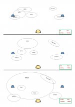
I found out that this effect it basically does exist while the DAC samplings frequency change. I mean the improvements still be there, with the caps in place, but is to be noticed a sound quality changes as the sampling frequency change. This is perfect normal. But the open sound stage and all the improvements this effect bring still be. The effect is not switched off by a lower sampling frequency. This is very clear for me now.
I have used for my experiment a very well recorded XRCD 24bit track, where the spatiality of the sound stage it were very carefully recorded, exactly for testing purposes.
First step: the CD track plaid as it is in its usual transport device, and the DAC set it up for 44,1Khz sampling
Second step: the CD track plaid as it is, and the DAC set it up for 192Khz.
Third step: the CD track extracted, oversampled to 176,4Khz wav 64bit, then converted to FLAC (64bit processing) to an 176,4Khz/24bit file. The file plaid (ASIO 64 bit) with the DAC set it up for 192Khz.
Unfortunately in my testing DAC system I could not access the 176,4Khz sampling step. But anyway, the improvements and the differences are obvious and only impressive, I can say.
I thought to illustrate graphically the results of my tests, so I attach the picture here. I do hope this illustration can clarify a little bit more about both the Rasmunssen effect and my tests...
There is of course a subjective part in this kind of testing. That because I still mean that if such tests are (will be) repeated by many other people, as there will be many to experiment on this effect, then for sure we will have more informations, and maybe quite well defined facts about.
BTW, this converting and oversampling process I used for this test it become a regular procedure for all my plaid and/or archived files. This process it give me the best possible (with the today consumer accessible digital technology) results. I do not use longer to play the CD recordings (I buy it...) as normal in a usual player device. I do convert first the tracks with this my (standard now) procedure, and then I use the files for playback, no matter the DAC system.
If one may be interested in this oversampling processing, one may get the "recipe/prescription"...
Well, I have done some (listening) tests in this respect.
I found out that this effect it basically does exist while the DAC samplings frequency change. I mean the improvements still be there, with the caps in place, but is to be noticed a sound quality changes as the sampling frequency change. This is perfect normal. But the open sound stage and all the improvements this effect bring still be. The effect is not switched off by a lower sampling frequency. This is very clear for me now.
I have used for my experiment a very well recorded XRCD 24bit track, where the spatiality of the sound stage it were very carefully recorded, exactly for testing purposes.
First step: the CD track plaid as it is in its usual transport device, and the DAC set it up for 44,1Khz sampling
Second step: the CD track plaid as it is, and the DAC set it up for 192Khz.
Third step: the CD track extracted, oversampled to 176,4Khz wav 64bit, then converted to FLAC (64bit processing) to an 176,4Khz/24bit file. The file plaid (ASIO 64 bit) with the DAC set it up for 192Khz.
Unfortunately in my testing DAC system I could not access the 176,4Khz sampling step. But anyway, the improvements and the differences are obvious and only impressive, I can say.
I thought to illustrate graphically the results of my tests, so I attach the picture here. I do hope this illustration can clarify a little bit more about both the Rasmunssen effect and my tests...
There is of course a subjective part in this kind of testing. That because I still mean that if such tests are (will be) repeated by many other people, as there will be many to experiment on this effect, then for sure we will have more informations, and maybe quite well defined facts about.
BTW, this converting and oversampling process I used for this test it become a regular procedure for all my plaid and/or archived files. This process it give me the best possible (with the today consumer accessible digital technology) results. I do not use longer to play the CD recordings (I buy it...) as normal in a usual player device. I do convert first the tracks with this my (standard now) procedure, and then I use the files for playback, no matter the DAC system.
If one may be interested in this oversampling processing, one may get the "recipe/prescription"...
Attachments
Last edited:
- Status
- Not open for further replies.
- Home
- Member Areas
- The Lounge
- DAC Filtering - the "Rasmussen Effect"