Suggestion for Voltage DACs:
This can of course be ICs as well, like an instrumentation circuit. The DAC will have its own output Z, hence determining the final cap value, what is shown is only a rough guesstimate.
Aim to adjust R and C values for a target of -1.3dB to -1.5dB @ 20KHz.
This time the cap is after the resistors, because a Voltage DAC is quite low Z. So it is reversed compared to Current DAC implementation.
Attachments
Last edited:
Suggestion for Voltage DACs:
This can of course be ICs as well, like an instrumentation circuit. The DAC will have its own output Z, so cap value is only an indicator.
So we agree that we are talking about a bog-standard RC circuit, and all we are discussing is what would explain the "sweet spot" behaviour?
So we agree that we are talking about a bog-standard RC circuit, and all we are discussing is what would explain the "sweet spot" behaviour?
Yes indeed. Being first order, it does what you normally don't see in a filter, that it will be noticeably down @ 20KHz - but the roll-off is very slow, so above 20KHz it is still well extended.
Please note this kind of filter cannot ring.
Pretty much every DAC I have seen from commercial sources, are pretty much flat @ 20KHz. I really can't think of any exception of the top of my mind. Aso, being just 0.5dB down @ 20KHz may actually make it sound worse, but keep going and it comes good.
Note again, we have only done this with delta-sigma DACs and don't expect other types of DACs to have this particular behaviour.
Cheers, Joe
Last edited:
Sabre DAC:
This is what I prefer to do - it is not Opamp based. Use your favourite analog circuit.
Depending on how many phases are paralleled, the output Z is between 780 Ohm and 195 Ohm. So the Sabre DAC is a little different, it has an offset voltage of 1.65V, but you can safely pull it to ground where the offset voltage become offset current, approx 2.1mA per phase.
This also works with Current DACs that have no DC offset, such as Burr-Brown, like PCM1792 etc. But do not use with Curren DACs that do have DC offset - like AD1955 etc.
Attachments
Last edited:
Yes indeed. Being first order, it does what you normally don't see in a filter, that it will be noticeably down @ 20KHz - but the roll-off is very slow, so above 20KHz it is still well extended.
Thanks for confirming that - hopefully that will settle one small part of the debate!
Interestingly I just read a review of the Elysia xfilter 500 studio equalizer in the latest issue of Audioxpress. A special feature of the device is a a function called "Passive Massage" that consists of a simple LC filter with small boost at 12 kHz and a gentle roll-off from 17 kHz. The effect was described as "creating a noticeable improvement on most sources" and "adds sheen and sparkle ... [and] ... enhances top-end response and improves the overall detail and clarity".
Please note this kind of filter cannot ring.
Indeed. But the capacitive loading might cause the preceding circuitry to oscillate.
It seems some guys here have tried this on passive IV, like :
DAC -> RC filter -> output
In this case, it is a simple linear passive filter and we can talk about frequency response. No problem here.
However when an opamp IV enters the picture it is a completely different thing. The following is about this case.
Let's spice it : a textbook OPA1632 I/V with 1mA differential current at the input, 1k IV resistors and 1nF feedback cap. -3dB point at about 160kHz.
Attachment 1 :
Sim with and without "C1" (3nF cap at the opamp input).
As expected the lowpass rolloff point does not change. All the cap does is add some nice peaking around 10 MHz.
Attachment 2 :
Same, with more "violent" values for C1, up to 100µF, stepped in decade. To get some change of frequency response in the audio band, at least 10µF is needed.
Coris, if you have a different circuit (making this sim irrelevant), please tell us about it.
Attachment 3 :
Transient simulation. No added capacitor.
Top curve, input current. Middle curve, voltage at opamp input. Bottom curve, output.
Opamp and its feedback caps behave as first order lowpass.
No problem here, everything behaves as expected. Which means it doesn't work : opamp goes in slew limit, input voltage is large, upsetting the opamp input stage, peaks of output voltage have ugly warts (see zoom insert), etc. That's the usual opamp IV, I guess that's why some don't like it...
Attachment 4 :
Transient simulation. Added capacitor at input.
Reduced phase margin makes opamp less stable. The input waveform is a mess. Output shows signs of ringing too.
Attachment 5 :
Removed feedback caps. Tweaked circuit values to get ringing similar to this trace.
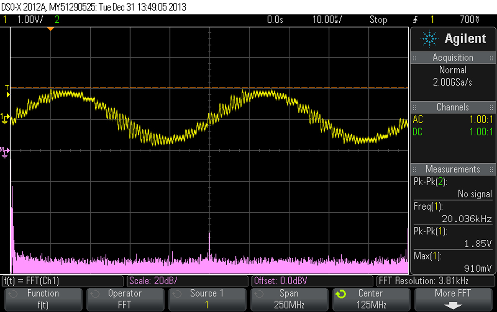
Thanks peufeu for the simulations and your work.
I can well recognize (out of my own measurements) and confirm almost all of these snap shots you have presented here. I was always and I `m using the last one design you have simulated (Opa1632, no feedback cap, almost the same R value, but the cap on input is 1n - no any other filtering, straight to the final opamp, 3x gain, and RCAs). This set up with that 1n across the 1792 DAC outputs it give me the right now the effect/improvement.
I can also get the same that bad signal (showed in my picture and to be seen in your 5 simulation) when I use a higher value cap (15n). Else everything is all right. Using that 15n cap in my set up it make the sound dumped, bass dominated, without sound space, but not at all (to be heard) distorted.
BTW, when I use resistors, as Joe shows in his last attachment for voltage set up, I get only a big mess for both how signal looks like, and how it sounds the outputted audio...
There is also true, and I can confirm here the zenelectro statements (thanks for clarifications and for your synthesis on subject), that increasing in HF noises occur in case of placing that cap, or when increasing its capacity value.
Even though all negative side effects when place a cap in that place, the improvements in sound quality and its sound space/stage are obvious and a fact. I do not know (yet) how we can get out of this dilemma, or how we can accept/treat these two simple opposite facts...😕
Last edited:
Okay, you agree that it is just a simple filter. Since everyone is hell-bent that I cannot know this (even though it's obvious), why don't you try this: Measure the F3 of your filter. Construct a simple RC with the same F3 and verify it. Now, do an A/B comparison of that. If anyone is unwilling to do that, they have no business telling me I must perform their experiment. Ken Newton, I'm looking at you.Yes indeed. Being first order, it does what you normally don't see in a filter, that it will be noticeably down @ 20KHz - but the roll-off is very slow, so above 20KHz it is still well extended.
No single pole filter can ring. However, if you push the op-amp to the point of instability by placing a capacitor in the location you place it at, the instability may look like ringing as the verge of oscillation is approaching.Please note this kind of filter cannot ring.
Joe you also state that I shouldn't be so condescending. You should know that several of us have stated what is going on here and you, Ken, and Coris, have crossed the line telling us not to post, calling us arm chair philosophers, and basically insulting anyone who does not agree with you. Perhaps you shouldn't take this as a personal war when established circuit analysis techniques do not agree with your claims.
You have a simple low-pass filter with F3 of about 30kHz. I don't see where the argument that it's not comes from.Sabre DAC:
This is what I prefer to do - it is not Opamp based. Use your favourite analog circuit.
Depending on how many phases are paralleled, the output Z is between 780 Ohm and 195 Ohm. So the Sabre DAC is a little different, it has an offset voltage of 1.65V, but you can safely pull it to ground where the offset voltage become offset current, approx 2.1mA per phase.
This also works with Current DACs that have no DC offset, such as Burr-Brown, like PCM1792 etc. But do not use with Curren DACs that do have DC offset - like AD1955 etc.
Also note that your peculiar placement of the capacitor increases the noise gain of the op-amp from 1 to Rf/3.3, this will dramatically increase the noise and that would explain the finding that that the signal looks different than a low-pass. It's now an extremely noisy single pole low-pass.
Last edited:
Thanks for confirming that - hopefully that will settle one small part of the debate!
That point has never been in debate. No one has ever suggested otherwise. The only debate has been over the rejection of the notion that merely setting a lower than normal (one falling in-band) filter roll-off point could produce an effect of particular interest, sound wise.
Okay, you agree that it is just a simple filter. Since everyone is hell-bent that I cannot know this (even though it's obvious), why don't you try this: Measure the F3 of your filter. Construct a simple RC with the same F3 and verify it. Now, do an A/B comparison of that. If anyone is unwilling to do that, they have no business telling me I must perform their experiment. Ken Newton, I'm looking at you...
Implementing a simple RC filter function is EXACTLY what we've been describing from the start. The ONLY parametric distinction talked about has been what that filter's response is at 20KHz. For whatever your reason, you keep attempting to distort that clear calm point in to some kind of claim of audio magic. Perhaps, less looking at others, and more looking at yourself is in order.
Last edited:
Sabre DAC:
This is what I prefer to do - it is not Opamp based. Use your favourite analog circuit.
It looks like an opamp circuit - there is feedback ! 🙂
Depending on how many phases are paralleled, the output Z is between 780 Ohm and 195 Ohm. So the Sabre DAC is a little different, it has an offset voltage of 1.65V, but you can safely pull it to ground where the offset voltage become offset current, approx 2.1mA per phase.
This also works with Current DACs that have no DC offset, such as Burr-Brown, like PCM1792 etc. But do not use with Curren DACs that do have DC offset - like AD1955 etc.
You can use either open loop current conveyor (844 / discrete) or opamp
based I-V for any of these DACs including AD1955.
The offset current must simple by nulled somewhere.
T
Sabre DAC:
This is what I prefer to do - it is not Opamp based. Use your favourite analog circuit.
Joe,
Your diagram appears to depict high closed-loop gain (feedback based) inverting op-amps (not necessarily monolithic devices, though). I note that your description describes the circuit as not feedback based. Can you clarify?
Last edited:
Again, you have distorted things to fit your own bias. You have repeatedly argued that there's more than a simple low-pass here, even to the point of stating that I must test it before posting a reply.Perhaps, less looking at others, and more looking at yourself is in order.
You should take your own advice. Re-read your own posts. You have vehemently denied that this is anything other than a simple low-pass to anyone who dare dispute your godly intellect in the matter.
However, I'm glad you finally agree that this is nothing but a low-pass filter. Whether this effect is audible or positive is subjective and I have no comments on what others hear.
I can hardly see your point FoMoCo.
There is here all about filtering. The title of the thread is quite clear about. This cap is a filter. Nobody argue on this. There is no any magic at all in using this kind of filtering. There are some facts, some people have experienced about, and is to be discussed here. There is quite clear, isn`t it?
There is here all about filtering. The title of the thread is quite clear about. This cap is a filter. Nobody argue on this. There is no any magic at all in using this kind of filtering. There are some facts, some people have experienced about, and is to be discussed here. There is quite clear, isn`t it?
Again, you have distorted things to fit your own bias. You have repeatedly argued that there's more than a simple low-pass here, even to the point of stating that I must test it before posting a reply.
You should take your own advice. Re-read your own posts. You have vehemently denied that this is anything other than a simple low-pass to anyone who dare dispute your godly intellect in the matter.
However, I'm glad you finally agree that this is nothing but a low-pass filter. Whether this effect is audible or positive is subjective and I have no comments on what others hear.
I now recognize what you are about. No, I won't play. Have a good day.
Last edited:
Coris, Ken, and Joe: Here's how the thread started.
Coris asked how this worked.
Julf explained:
You said that wasn't the case:
I also said it was a simple filter:
Then Joe agrees that it's a filter but implies that it's different than a simple single pole low-pass:
Coris doesn't like my assertion that it's a simple filter and says so:
Ken disagrees and wants to know why he sees differently:
Some discussion between all ensues and Ken belts out this gem, insisting that I am "blindly theorizing" even though this is a simple textbook problem at this point:
The actual effect is disputed by several and Ken admonishes the dissenters to not post unless they try his requisite experiment:
Ken tells another dissenter the same:
Flustered in the ensuing argument, Ken bandies about insults and says he'll stop the back-n-forth. But, later we see he doesn't.
From this point it just gets nasty for all that disagree.
Finally Joe jumps in condemning the dissenters:
The more I re-read this, I think Joe has not read the entire argument and thinks we are saying that he didn't hear anything and is a bit insulted by that. I took it as he was still disputing the claim of a simple filter when he was accusing those who were disagreeing of being arm chair dissenters or similar. This includes the admonishment is this long post:
Note that Joe does agree that it's a simple filter, even though it's been snipped out.
Next, Ken continues to argue even though he said earlier he wasn't going to. He even throws in some "advice" that is really an insult:
Finally he spews this:
Ken, I now recognize what you're all about. I won't play either.
I also see that Joe agrees that this is a simple filter. There's nothing for me to dispute about that. I personally don't think I'd hear it. But, I can't say that anyone else won't.
Joe: If you did indeed think that I implied that you couldn't hear a difference, I apologize. I was too busy fighting with Ken and Coris about whether it was a filter or not.
Coris and Ken: Bite me. No need for insults because you don't agree. Especially you Ken, you crossed a line telling anyone not to post. You aren't a moderator here.
Note: Even though I snipped the quotes, you can click them to see them in their entirety.
Coris asked how this worked.
How it works this filtering?
Not really known so far... Just speculations, and few attempts for answers...
Julf explained:
Doesn't that just form a first-order low-pass filter?
You said that wasn't the case:
Yes, it seems like a first-order low-pass filter... But it differ than a usual low pass filter placed on each phase of a DAC, and it looks like the result of this filtering is different...
I also said it was a simple filter:
No it isn't. It's a single pole lowpass. If by phases you mean the differential output, it's still a single pole, just differential instead of common mode.
Then Joe agrees that it's a filter but implies that it's different than a simple single pole low-pass:
ow that I have gotten that out of the way, then to answer your question - that a single-pole dominant filter (dominant as the very slow slope intrudes on what we normally think in a way unacceptable, it is not flat @20KHz and over-rides every other filter in the chain) has an unusual sweet spot and is not just about suppressing HF noise, although that may well be part of the answer too
Coris doesn't like my assertion that it's a simple filter and says so:
Sorry for heaving just opposite opinion than you...
Ken disagrees and wants to know why he sees differently:
In linear systems theory, yes. However, no linear theory I know would seem to explain the observed behavior this effect. So, it would be interesting to confirm.
Some discussion between all ensues and Ken belts out this gem, insisting that I am "blindly theorizing" even though this is a simple textbook problem at this point:
That's one theory. However, rather than blindly theorizing, perhaps, you would be better served by first trying such a simple to perform experiment.
The actual effect is disputed by several and Ken admonishes the dissenters to not post unless they try his requisite experiment:
Here's what I will suggest. If you won't first try this rather simple experiment, that's your prerogative, but do not waste your time (or mine) commenting in this thread? There is a difference between healthy skepticism and closed-mindedness.
Ken tells another dissenter the same:
Julf, see my post #46 comment to FoMoCo, as it applies to you as well.
Flustered in the ensuing argument, Ken bandies about insults and says he'll stop the back-n-forth. But, later we see he doesn't.
You, apparently, have a reading comprehension problem. Not to mention, the evident need to be argumentative. There's nothing to be gained in our continuing this sort of back-and-forth. So, I will stop.
From this point it just gets nasty for all that disagree.
Finally Joe jumps in condemning the dissenters:
There will be further skepticism I know... but gradually, the more who do it, then the number of armchair critics will diminish.
The more I re-read this, I think Joe has not read the entire argument and thinks we are saying that he didn't hear anything and is a bit insulted by that. I took it as he was still disputing the claim of a simple filter when he was accusing those who were disagreeing of being arm chair dissenters or similar. This includes the admonishment is this long post:
In the meantime, please don't sound so condescending, please...... OK?
Note that Joe does agree that it's a simple filter, even though it's been snipped out.
Next, Ken continues to argue even though he said earlier he wasn't going to. He even throws in some "advice" that is really an insult:
For whatever your reason, you keep attempting to distort that clear calm point in to some kind of claim of audio magic. Perhaps, less looking at others, and more looking at yourself is in order.
Finally he spews this:
I now recognize what you are about. No, I won't play. Have a good day.
Ken, I now recognize what you're all about. I won't play either.
I also see that Joe agrees that this is a simple filter. There's nothing for me to dispute about that. I personally don't think I'd hear it. But, I can't say that anyone else won't.
Joe: If you did indeed think that I implied that you couldn't hear a difference, I apologize. I was too busy fighting with Ken and Coris about whether it was a filter or not.
Coris and Ken: Bite me. No need for insults because you don't agree. Especially you Ken, you crossed a line telling anyone not to post. You aren't a moderator here.
Note: Even though I snipped the quotes, you can click them to see them in their entirety.
I see this thread as an investigation of a tweak that leads to a psychoacoustic improvement in the sound. This effect seems to be different to what would be expected from a 1st order filter that it is worth investigating it further.
Some may not be interested in so doing but I believe that there is enough interest (nearly 30,000 views) to see where this finally leads, wherever that might be.
Some may not be interested in so doing but I believe that there is enough interest (nearly 30,000 views) to see where this finally leads, wherever that might be.
Could I ask some questions related to the confusion which Zenelectro mentioned
- Is this effect only operational when the output stage involves an opamp (as there is a well known trick of using a cap across the differential inputs of an opamp)
- Ken also mentioned that this effect also works on the SE output of his 1794 DAC so is this applicable to any SE output DAC?
- does the sharp turn on of the effect suggest some mechanism which is attenuating the pre-ringing of most linear phase digital filters?
I see this thread as an investigation of a tweak that leads to a psychoacoustic improvement in the sound. This effect seems to be different to what would be expected from a 1st order filter that it is worth investigating it further.
Some may not be interested in so doing but I believe that there is enough interest (nearly 30,000 views) to see where this finally leads, wherever that might be.
That because it will be a benefit for the investigations, and eventual further conclusions, if many may try to find out more by themselves, experimenting and appreciate the results with their knowledge. As Ken did, myself and so on.
If one own a DAC system (and the most of the members here does), then can one extremely easy experiment with this effect.
About the effect is primary to experience it, and then analyse in detail the results.
I`m quite reserved to call the effect as a "psychoacoustic" phenomenon. There may be enough strange if few people, in so different places, who never meet each other before, can have almost the same experiences in implementing this trick. It have to be a fact in all this, and not only some psycho...
By experimenting with different types DACs it may come the answers for few of your already precise questions...
......
I`m quite reserved to call the effect as a "psychoacoustic" phenomenon. ,,,,,
I don't mean to use this term "psychoacoustic" in any negative way. The term psychoacoustic to me means any difference in the analogue output that gives rise to an audible difference in the sound & does not mean it is an "imagined" or "purely psychological effect"
- Status
- Not open for further replies.
- Home
- Member Areas
- The Lounge
- DAC Filtering - the "Rasmussen Effect"