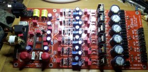
Hi Quanghao, I have a problem with the power stage circuit in the 260V SSHV specifically, since there is only the 61V output.
I have attached some pictures where you can see the component values that have been used and the voltages obtained.
Thanks.
please change new IRF 9610 and 3 led.
measure the V on R1 = 1.8 to 2.1v, it is good!
thanks
Hi Quanghao,
I changed the IRF9610 and the 3 LEDs with a new one.
I measured the voltage on R1 33ohm = 18V.
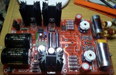
I have two PCB mounted and the problem is the same in both.
Only 82 V at the output.
What is the correct value to R12 and R4? in Scheme R12 = 270K (1W) R4 = 120K (2W). R12 on the PCB is R8 = 220K (1W) R4 = 180K (2W).
R3 56K in Scheme (5W) PCB (R3 = 180K, R3B = 180K, R3C = 180) Total = 60K.
For 56K (R3 = 180K, R3B = 180K, R3C = 150K) Total = 56K250.
Have you tried the new PCB? I do not understand where the problem is.
Thanks.
I changed the IRF9610 and the 3 LEDs with a new one.
I measured the voltage on R1 33ohm = 18V.
I have two PCB mounted and the problem is the same in both.
Only 82 V at the output.
What is the correct value to R12 and R4? in Scheme R12 = 270K (1W) R4 = 120K (2W). R12 on the PCB is R8 = 220K (1W) R4 = 180K (2W).
R3 56K in Scheme (5W) PCB (R3 = 180K, R3B = 180K, R3C = 180) Total = 60K.
For 56K (R3 = 180K, R3B = 180K, R3C = 150K) Total = 56K250.
Have you tried the new PCB? I do not understand where the problem is.
Thanks.
Last edited:
hello Quanghao,
I think I found the problem resistor R1 = 33 Ohm, in the two PCBs were cut could not imagine that 2 of 33 ohm resistors Dale new were defective.
On Monday I will see if it works well now I have 33 Ohm resistors. Sorry I bothered by this problem.
Thank you.
I think I found the problem resistor R1 = 33 Ohm, in the two PCBs were cut could not imagine that 2 of 33 ohm resistors Dale new were defective.
On Monday I will see if it works well now I have 33 Ohm resistors. Sorry I bothered by this problem.
Thank you.
hello Quanghao,
I think I found the problem resistor R1 = 33 Ohm, in the two PCBs were cut could not imagine that 2 of 33 ohm resistors Dale new were defective.
On Monday I will see if it works well now I have 33 Ohm resistors. Sorry I bothered by this problem.
Thank you.
Hi how it work??
thank
Quanghao, guys,
my transport provides a balanced output, so I would like to use DAC END XLR input.
Did you test XLR input? Does balanced connection works?
Thanks all
Andrea
my transport provides a balanced output, so I would like to use DAC END XLR input.
Did you test XLR input? Does balanced connection works?
Thanks all
Andrea
Quanghao, guys,
my transport provides a balanced output, so I would like to use DAC END XLR input.
Did you test XLR input? Does balanced connection works?
Thanks all
Andrea
yes, but you not use toslink.
thanks
hello Guanghao,
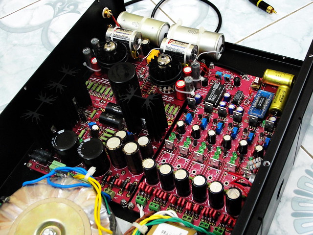
the sound is very nice and fairly compensated, thanks to Andrea, and to you for the work you have done.
Just one more question I have installed the 5687 and point B I have 144V. and point P 51V. is that correct?.
without putting the Tubes I have in the point B 260V.
thanks
the sound is very nice and fairly compensated, thanks to Andrea, and to you for the work you have done.
Just one more question I have installed the 5687 and point B I have 144V. and point P 51V. is that correct?.
without putting the Tubes I have in the point B 260V.
thanks
Last edited:
hello Guanghao,
the sound is very nice and fairly compensated, thanks to Andrea, and to you for the work you have done.
Just one more question I have installed the 5687 and point B I have 144V. and point P 51V. is that correct?.
without putting the Tubes I have in the point B 260V.
thanks
no!
if not use LL1660 out put,
So the V at +B 250 to 260V, The vol at Anode at 90 to 100V. thanks
Hi,yes, but you not use toslink.
thanks
do you mean don't use both at the same time?
or don't install TORX?
Andrea
Andrea _mori
don't install TORX
the Torx and the XLR Balanced are connected in parallel to the relay
don't install TORX
the Torx and the XLR Balanced are connected in parallel to the relay
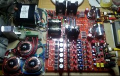
hi Quanghao, I have not found schematic for your stage iv board, this is one dated 15/9/2011 and has lots of diodes on it which are not speficied. as well as 4 jumper wires.
Can you kindly post a scheuatic for this sshu LL1660 iv stage board. thanks, John
Can you kindly post a scheuatic for this sshu LL1660 iv stage board. thanks, John
hi Quanghao, I have not found schematic for your stage iv board, this is one dated 15/9/2011 and has lots of diodes on it which are not speficied. as well as 4 jumper wires.
Can you kindly post a scheuatic for this sshu LL1660 iv stage board. thanks, John
you use 2 jum follow:
jum 6H if you use tube 6Dj8, 6h30
Jum 5687 for 5687 and el82cc, or bandix 6900
thank
Beautiful! Reminds me of my 'old' DAC END 😀Just finished, to be tested
Hi all! Who bought the components here, the original?
CS8414 CS8414CS CS8414 CS 96K Digital Audio Receiver Soldered on DIP Adapter | eBay
1pcs AD1865 AD1865N AD1865N K Dual 18bit 16XFS DAC DIP 24 Adi Brand New | eBay
CS8414 CS8414CS CS8414 CS 96K Digital Audio Receiver Soldered on DIP Adapter | eBay
1pcs AD1865 AD1865N AD1865N K Dual 18bit 16XFS DAC DIP 24 Adi Brand New | eBay
Attachments
- Home
- More Vendors...
- Quanghao Audio Design
- DAC-END The best DAC AD1865- UPDAT 2011