In the near future will be available a module to modify the configuration of the ES9018 with infrared remote control.
The main functions:
- input selection spdif, toslink, dsd and i2s
- volume
- mute
The main functions:
- input selection spdif, toslink, dsd and i2s
- volume
- mute
Last edited:
In the near future will be available a module to modify the configuration of the ES9018 with infrared remote control.
The main functions:
- input selection spdif, toslink, dsd and i2s
- volume
- mute
hi! audiodesign , you finis write code for volume DAC!
thanks
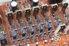
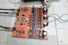
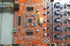
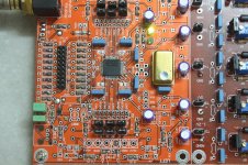
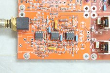
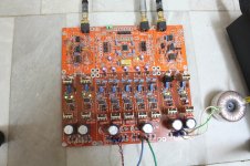
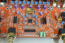
I have complete kit DAC-END 32, I am very pleased with the sound of it!
Invite the doctor to see the pictures!
Thanks
Invite the doctor to see the pictures!
Thanks
Attachments
-
 IMG_0116.JPG334 KB · Views: 1,407
 -
 IMG_0120.JPG554.5 KB · Views: 1,329
 -
 IMG_0123.JPG685 KB · Views: 1,245
 -
 IMG_0126.JPG722.6 KB · Views: 1,155
 -
 IMG_0131.JPG355.1 KB · Views: 1,071
 -
 IMG_0143.JPG570.5 KB · Views: 288
 -
 IMG_0153.JPG446.7 KB · Views: 306
 -
 IMG_0168.JPG506.2 KB · Views: 311
 -
 IMG_0178.JPG590.6 KB · Views: 344
Looking for a good I/V for this project I have started a series of test with output transformers.
There is another thread about ES9018 and transformers.
http://www.diyaudio.com/forums/twisted-pear/164294-buffalo-ii-transformers.html
The trasformers can be placed bofore or after the resistors of the I/V.
I have modified the schematic of Joe Rasmussen.
There is another thread about ES9018 and transformers.
http://www.diyaudio.com/forums/twisted-pear/164294-buffalo-ii-transformers.html
The trasformers can be placed bofore or after the resistors of the I/V.
I have modified the schematic of Joe Rasmussen.
Attachments
The 200ohm should seen on primaries like a 200 / (4 * 4) = 12.5 ohm
but if we add also the static resitance of the primaries and secondaries
the new calculation give:
(200 + 605 + 605 / (4 * 4)) + (33 + 33) = 154 ohm (to divide for 2 prim.)
so probably the frequency response is better with the I/V resistor after the transformer becasue the ES9018 is working in voltage and not current.
Attachments
Last edited:
I will make some more test with LL1684 1+1:1 this evening but until now I don't consider a good idea to use the transformer on output of ES9018.
The frequency response is too bad on low frequency.
The frequency response is too bad on low frequency.
I used a pair of Jensen output transformers directly connected to the ES9018 output and was quite happy with the sound. I selected the Jensen because they seemed to be built on science and theory not snake oil. Jensen also has a well written book on audio transformers on their website. I used the JT-10KB-D step down transformer to give me 0.6 V output, which was perfect for the gain of my amp. Also, I picked a slightly higher resistance than recommended on the output and loaded it with my amp input impedance in parallel to give the right value. It worked really well and I was quite happy with the low end. I had tried another configuration with an I/V stage before the transformer but found the low end frequency response to be rolled off. Maybe just try different configurations with the transformers you have to see if you can get the sound you are looking for.
reactivepower, Have you measure it ?
Many DIY use transformers without measurements and they think to ear a good sound but in reality they are losing many details because there is many problems on frequency response.
Certainly I don't know if you have these problems and I don't know if you are using the ES9018 as voltage output.
The trasformes and choke have many many bad effects on frequency band and only with a set of measurements these can be found.
To create a set of measurements is necessary only a normal sound card and the freeware Arta software.
I used a pair of Jensen output transformers directly connected to the ES9018 output and was quite happy with the sound. I selected the Jensen because they seemed to be built on science and theory not snake oil. Jensen also has a well written book on audio transformers on their website. I used the JT-10KB-D step down transformer to give me 0.6 V output, which was perfect for the gain of my amp. Also, I picked a slightly higher resistance than recommended on the output and loaded it with my amp input impedance in parallel to give the right value. It worked really well and I was quite happy with the low end. I had tried another configuration with an I/V stage before the transformer but found the low end frequency response to be rolled off. Maybe just try different configurations with the transformers you have to see if you can get the sound you are looking for.
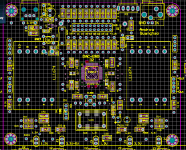
I plan to do the PCB has the following output:
1. DAC output signal directly-you can use the manufacturer's standard IV with 3 opam A797.
2. DAC using the or iV Output used a pre opam or tube
3. DAC output signal through a transformer LL1674 or equivalent. You can buy it and add your own.
I plan to do the PCB has the following output:
1. DAC output signal directly-you can use the manufacturer's standard IV with 3 opam A797.
2. DAC using the or iV Output used a pre opam or tube
3. DAC output signal through a transformer LL1674 or equivalent. You can buy it and add your own.
1. DAC output signal directly-you can use the manufacturer's standard IV with 3 opam A797.
2. DAC using the or iV Output used a pre opam or tube
3. DAC output signal through a transformer LL1674 or equivalent. You can buy it and add your own.
Attachments
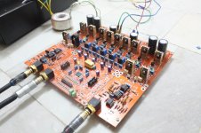
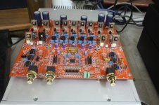
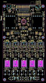
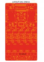
and this is the lyout part complete DAC-end R.with the following dimensions:
110 mm x 210 mm.
I plan to do with all kit components paste, used industrial welding machines.
Note that the kit is not LL1674 transformer, you need to purchase it separately and welding kit.
You look at this project, thank you!
110 mm x 210 mm.
I plan to do with all kit components paste, used industrial welding machines.
Note that the kit is not LL1674 transformer, you need to purchase it separately and welding kit.
You look at this project, thank you!
Attachments
Last edited:
Looking for a good I/V for this project I have started a series of test with output transformers.
There is another thread about ES9018 and transformers.
http://www.diyaudio.com/forums/twisted-pear/164294-buffalo-ii-transformers.html
The trasformers can be placed bofore or after the resistors of the I/V.
I have modified the schematic of Joe Rasmussen.
Hello !
Speaking about left D schematic (resistors on primary):
Did you test also, but without grounding CT on primary ?
I didn't have measured, but to "my ears", it sound better with only one resistor (6 ohms) across primary, and x50 tube stage.
Thanks
Richard
yes, i use the iv passive 5R ( parallel 2x 10R) but i not use out put tranformer, I use balnce op am. the sound i like!Hello !
Speaking about left D schematic (resistors on primary):
Did you test also, but without grounding CT on primary ?
I didn't have measured, but to "my ears", it sound better with only one resistor (6 ohms) across primary, and x50 tube stage.
Thanks
Richard
Thanks
Hello !
Speaking about left D schematic (resistors on primary):
Did you test also, but without grounding CT on primary ?
I didn't have measured, but to "my ears", it sound better with only one resistor (6 ohms) across primary, and x50 tube stage.
Thanks
Richard
Where you connect the central ?
Where you connect the central ?
Hello !
I don't have any central .... I use Jensen JT-11-emcf transformer
The resistor is across the primary, the + - are always 180° of phase, so the current is flowing, and as ESS said early, the ESS9018 output is "sourcing/sinking"
Would you explain the "theory" with CT grounded, and if you could test, it would be nice
Thanks
If we use the tranformer we don't need a balanced differential vacuum tube stage so we could use this circuit.
It is a variation of the TEM 3200 6moons audio reviews: Thorens TEM 3200
It is a DC coupled vacuum tube stage without the output capacitor.
The negative voltage is variable with an auto-set to get always zero volt on output.
The second stage is driven on g2 grid and the low global feedback is optional not necessary.
Attachments
Last edited:
- Status
- Not open for further replies.
- Home
- Source & Line
- Digital Source
- DAC-END R (ES9018)