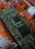
I have covered the USB connector's pin 1 (Vcc pin) with a tape and powered the Amanero with DAC power, it works, no removal of LDO is needed.
I don't like very well your USB solution.
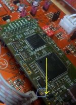
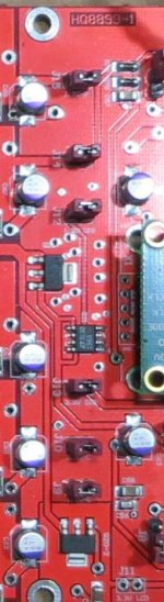
I suggest cut the pcb wire, very simple.
Attachments
Last edited:
Hi,
I have raised this pin of the regulator from the printed circuit board with a cutter blade.
- So, if needed, I can weld it next time and the board remain like new.
I have raised this pin of the regulator from the printed circuit board with a cutter blade.
- So, if needed, I can weld it next time and the board remain like new.
Attachments
Last edited:
Hi,
I have raised this pin of the regulator from the printed circuit board with a cutter blade.
- So, if needed, I can weld it next time and the board remain like new.
I removed the part, which I now regret, yours is a better solution.
Hello,
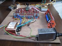
My DAC implementation (breadboard 😉 ) was very sensitive to the mains: if I switched on/off a lamp or my soldering station I had drop outs.
So I installed a netfilter I had laying around: much better, no more dropouts.
Nice, netfilters that really do work 🙂
Regards,
Danny
My DAC implementation (breadboard 😉 ) was very sensitive to the mains: if I switched on/off a lamp or my soldering station I had drop outs.
So I installed a netfilter I had laying around: much better, no more dropouts.
Nice, netfilters that really do work 🙂
Regards,
Danny
Attachments
Quanghao, can you send my dac early next week and with the latest firmware version? Thanks
yes!
some day later i will ship it!
thanks you waite!~
Hello
I still have problem with heat. Tryed 15 and 22 Ohm resistors instead of 10 Ohm but it is only 5 - 10 % beter.
Still not OK. Allso I have LOT of NOISE / RIPPLE on power supply lines.
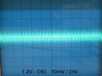
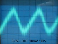
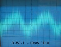
Here are puctires. All is measured on JUMPERS J9 - J10 - ..... - J15 .
1.2V - L picture is with original resistor
1.2V - R picture is with 22 Ohm resistor
I still have problem with heat. Tryed 15 and 22 Ohm resistors instead of 10 Ohm but it is only 5 - 10 % beter.
Still not OK. Allso I have LOT of NOISE / RIPPLE on power supply lines.
Here are puctires. All is measured on JUMPERS J9 - J10 - ..... - J15 .
1.2V - L picture is with original resistor
1.2V - R picture is with 22 Ohm resistor
Attachments


Which power supply line ? 1.2V analog ?
Do you meausre with load or without (jump open or closed) ?
Do you meausre with load or without (jump open or closed) ?
Hello
Oh, no,no
you not can big up all R 10 Ohm to 22 Ohm, you need keep all 10 ohm.
If you need down more noise , you can down the value under 10 Ohm,
You can use : 8 to 10R. Because the curent = 06 / 10 R ( r-set current )
you see??
thanks
this noise is 10 x bigger than LM317 noise.
off course I want it down
will test 8.2 ohm in 5 minutes
off course I want it down
will test 8.2 ohm in 5 minutes
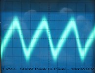
8.2 Ohm make Bigger noise = 60 mV Peak to Peak
10 Ohm = 50 mV p - p
22 Ohm make Less noise = 40 mV p - p
HEAT stays same
10 Ohm = 50 mV p - p
22 Ohm make Less noise = 40 mV p - p
HEAT stays same
this noise is 10 x bigger than LM317 noise.
off course I want it down
will test 8.2 ohm in 5 minutes
We cannot speak of noise because each power supply have a pre regulator followed by a shunt.
You need to test the noise on output terminals not on power jump otherwise you can create oscillation on shunt.
I put mine in the basement until next year when problems are solved ---maybe ?
Yes do that, then we're relieved of your constructive remarks 😉
Yes do that, then we're relieved of your constructive remarks 😉
I have severeal ideas but cannot measure oscilations and noise. Twisted pear had similar problems and bigger caps on output helped. More then 100 uf.I am planning to use 1000 uf. I know some off you will tell it is not good on shunts. I always put more both on out and input off regulators. They have to be closer to the shunt output. I will trow the 10 uf ceramics away. Also the ceramics by the opamps is gone allready.
Last edited:
Hello
I still have problem with heat. Tryed 15 and 22 Ohm resistors instead of 10 Ohm but it is only 5 - 10 % beter.
Still not OK. Allso I have LOT of NOISE / RIPPLE on power supply lines.
Here are puctires. All is measured on JUMPERS J9 - J10 - ..... - J15 .
1.2V - L picture is with original resistor
1.2V - R picture is with 22 Ohm resistor
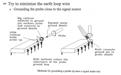
Hi there
Just to verify the measurement is correct. Please make a measurement as described in this pic. This will lower the noise that is introduced by the GND wire on the Scope Probe.
What frequency is the ripple?
Best Regards
Caad
Attachments
Power supply noise
We cannot speak of noise in the main DAC module because we have a 2 stage power supply.
A pair of LT1963 ultra low noise linear regulators create the +5V for digital section and the +5V for analog sections.
These regulators are followed by other linear regulators or hi-speed op-amp controller shunt.
All the following measurements has been created with Clio system by Audiomatica and Transit 24bit.
There is no noise on output terminal (-78dB), see file Noise_DACout, 50Hz at -82dB coming from the air.
Also if I connect the 2.2uF input cap. to the ground I see 50Hz at -82dB.
There is a little oscillation on 1.2analog shunt (about 15KHz at -36dB), see file Noise_1_2ana.
If you add a 100uF 6.3V in parallel to the 47uF smd this oscillation stop and the new measurement give -78dB.
The other shunt have no oscillation and also the 15V shunt without pre-regulator are able to eliminate any noise, (50-100Hz at -80dB).
Attachments
Last edited:
- Status
- Not open for further replies.
- Home
- More Vendors...
- Quanghao Audio Design
- DAC-END R (ES9018) full assembled board