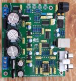
Well, like dozens of other "made in china" DAC it all comes down to two things, upgrading the power supply and upgrading the output stage...
Changing the existing components with better/more expensive ones will only get you so far. The next bigger modification would be to change the
complete power supply section and output stage. However not everyone has enough knowledge/experience to try something more complicated, non
the less, for those willing to try here is a short tutorial;
bla.... bla.... bla....
If anyone wants to try and build this, I'll help as much as I can, so
questions are welcome...
8 years later... 😀
After a long absence from the forum, I saw there were a few PM's with request for files from the original post...
So, here they are, re-uploaded in one .zip file: Dropbox - dac-cs4398-cs8416.zip - Simplify your life, as i can't edit the original post to fix the links...
Nice work, @ch33ta. Shunt regulators etc.
Would not it be easier just to create PCB from the scratch? And add DSD support?
I know I know this IC is a bit out of date but it sounds really good in my twiked LJM DAC for a few years ) Now I prefer AK4490/4493
Regards,
Vladimir
Would not it be easier just to create PCB from the scratch? And add DSD support?
I know I know this IC is a bit out of date but it sounds really good in my twiked LJM DAC for a few years ) Now I prefer AK4490/4493
Regards,
Vladimir
Well this was the first DAC i built and modded to this extent.
For the price it was pretty good sound-wise and easy to mod/build.
Later I ended up on WM8741 with custom built PCB and regulator, UTC A-20 for output and WaveIO for USB to I2S conversion.
For now it's enough for me...
Regards,
Ivan
For the price it was pretty good sound-wise and easy to mod/build.
Later I ended up on WM8741 with custom built PCB and regulator, UTC A-20 for output and WaveIO for USB to I2S conversion.
For now it's enough for me...
Regards,
Ivan
Hi all,
Apologies for what I expect to be a rambling post.
I'm building my kit of this board. I've noticed a few differences on it from the schematics and images of other users boards and would welcome any thoughts on whether to go with the boards silkscreen markings or what has been used before.
1. No 75ohm resistor - however I have the optical input board and I suspect the 75ohm resistor is there for impedance matching for the coax version of the board. As such, I suspect the resistor isn't required?
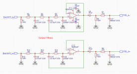
2. The 2.2nF (222) capacitors have been replaced with 100nf (104) capacitors. I can't identify the filter type topology (it's almost a low pass filter of a high value across the + and - output to the NE5532?) and so can't suss the likely frequency range affected 🙁 2.2nF or 100nF in this position?
3. Is there any benefit from impedance matching the line output to my amplifier's input - which listed as 15K ohms?
Thanks in advance - and please don't notice the capacitor I accidentally caught with the soldering iron whilst distracted (the odour was quite something). It will be replaced.
Apologies for what I expect to be a rambling post.
I'm building my kit of this board. I've noticed a few differences on it from the schematics and images of other users boards and would welcome any thoughts on whether to go with the boards silkscreen markings or what has been used before.
1. No 75ohm resistor - however I have the optical input board and I suspect the 75ohm resistor is there for impedance matching for the coax version of the board. As such, I suspect the resistor isn't required?
2. The 2.2nF (222) capacitors have been replaced with 100nf (104) capacitors. I can't identify the filter type topology (it's almost a low pass filter of a high value across the + and - output to the NE5532?) and so can't suss the likely frequency range affected 🙁 2.2nF or 100nF in this position?
3. Is there any benefit from impedance matching the line output to my amplifier's input - which listed as 15K ohms?
Thanks in advance - and please don't notice the capacitor I accidentally caught with the soldering iron whilst distracted (the odour was quite something). It will be replaced.
Attachments
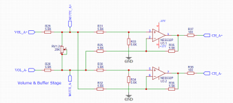
I'm working on a balanced output stage and volume control for this DAC.
I was wondering if anyone could peer review my schematic and comment on possible pitfalls or improvements.
Schematics only show 1 channel.
First comes the balanced filter stage. Input comes straight from the DAC chip. I've duplicated the balanced output filter schematic I found in the datasheet of the CS4398 evaluation board.
After that comes a volume pot (which I hope is connected correctly for balanced volume control). Followed by a differential buffer stage.
Attachments
Well this was the first DAC i built and modded to this extent.
For the price it was pretty good sound-wise and easy to mod/build.
Later I ended up on WM8741 with custom built PCB and regulator, UTC A-20 for output and WaveIO for USB to I2S conversion.
For now it's enough for me...
Regards,
Ivan
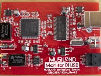
Hello I have the same kit. Could you tell which input board did you use?
Attachments
Hello I have the same kit. Could you tell which input board did you use?
That would be the Musiland Monitor 01 USD.
Used it to get SPDIF from PC, but later skipped the unnecessary/unwanted conversion and went PC -> I2S -> DAC chip with much better WaveIO board.
Attachments
Thanky you.
Do you think I could use this module?
Lusya XMOS XU208 Asynchronous USB Coaxial Fiber Output Digital Interface IIS DSD256 Spdif Dop64 With Acrylic Sheet A6 018|Digital-to-Analog Converter| - AliExpress
XMOS XU208 Asynchronous USB Coaxial Fiber Output Digital Interface IIS DSD256 Spdif Dop64 With Acrylic Sheet A6-018
Yes, I don't see a reason why it shouldn't work...
However, with a price of 69€ I would rather go with a little more expensive (99€) WaveIO. Keep in mind that USB drivers also play a big role for a device like that, so do your homework before buying. Just my 2 cents... 🙂
However, with a price of 69€ I would rather go with a little more expensive (99€) WaveIO. Keep in mind that USB drivers also play a big role for a device like that, so do your homework before buying. Just my 2 cents... 🙂
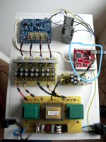
Hello I have ordered the new WaveIO USB Interface from this website:
Home
I have seen from your bild that you are using just USB interface and you removed some components , which you did not need.
I would like to use as USB interface the new WaveIO and the existing Coaxial interface. Is there any scheme for these modifications?
Can someone give me a link?
Thansk
Home
I have seen from your bild that you are using just USB interface and you removed some components , which you did not need.
I would like to use as USB interface the new WaveIO and the existing Coaxial interface. Is there any scheme for these modifications?
Can someone give me a link?
Thansk
Hello I have ordered the new WaveIO USB Interface from this website:
Home
I have seen from your bild that you are using just USB interface and you removed some components , which you did not need.
I would like to use as USB interface the new WaveIO and the existing Coaxial interface. Is there any scheme for these modifications?
Can someone give me a link?
Thansk
Just skip the SPDIF interface, if you are using a WaveIO board for USB interface it's an unnecessary conversion to SPDIF and then back to I2S, also the difference in sound is noticeable.
Also, if you have the same board as on the image above, only part that was striped from the DAC board was the power supply section, which was replaced with low noise regulators...
THanks for your quick reply. I did not explain myself right. I want to use the DAC also for my CD player and so I need teh coaxial SPDIF interface...
Hell, next week i should Receiver the waveio USB input Board. I have built the Prototype and still Testing with one Channel and original output Filter . Discrete stage not yet Testes. I am using the spdif output of the CD player. When a Song Is in pause or It Changes Tracks there Is a noi se nad the "locked" led flickers...
What Is the Problem?
What Is the Problem?
Attachments
Hello, pardon if I bother you with so many questions, but I think I am almost done.Just skip the SPDIF interface, if you are using a WaveIO board for USB interface it's an unnecessary conversion to SPDIF and then back to I2S, also the difference in sound is noticeable.
Also, if you have the same board as on the image above, only part that was striped from the DAC board was the power supply section, which was replaced with low noise regulators...
Now that I have the interface made from Lucian WaveIO I can have an I2S output as you wrote.
In the images of your set up, I see you take the signal with a coaxial cable to the spdif input of the CS8416. Probably is an old image and you did not mean this, also because the interface was not a WaveIo.
At the end shall I connect :
- DT --> SDIN Serial data Input
- LR --> LRCK Left Right Clock
- BC --> SCLK Serial Clock
- MC --> MCLK Master Clock
Thanks so much🙂
This DAC with mod is would be better sound than an original? I already listen in last year a stock version with Nichicon FG and R-Core trans. The sound was good but there is no dsd and only 44/16 via USB.8 years later... 😀
After a long absence from the forum, I saw there were a few PM's with request for files from the original post...
So, here they are, re-uploaded in one .zip file: Dropbox - dac-cs4398-cs8416.zip - Simplify your life, as i can't edit the original post to fix the links...
Is it worth to bulid this DAC with mod? What it gives?
Thanks
Sorry for my english (it's not my native language)
In fact, 16 bit 44K is very good.This DAC with mod is would be better sound than an original? I already listen in last year a stock version with Nichicon FG and R-Core trans. The sound was good but there is no dsd and only 44/16 via USB.
Is it worth to bulid this DAC with mod? What it gives?
Thanks
Sorry for my english (it's not my native language)
I have many 24 bit 192k 384K DAC.
In fact, there is no improvement in sound quality.
All CDs are 16bit 44K. Isn't CD sound good.
The current 192K 384k. In fact, it's just commercial advertising.

You can see anything you want.@ljm_ljm Can I see your complete Dac inside?
I just don't know English very well. I don't understand what you mean
I mean boards with details which already connected to amp.You can see anything you want.
I just don't know English very well. I don't understand what you mean
- Home
- Source & Line
- Digital Line Level
- DAC: CS4398 with CS8416+CM102s