Great. generous power supply. Mine is not such 🙁
I made first tests. To adjust voltages just with resistors, was tricky job. Must take in mind, that increased chokеs drop the voltage. I adjusted at 2 steps. First with load resistors 100 ohms after the chockе, and next with ICs on place. For now, good. SAA7220 is warm. May be normally - 180mA.
I made first tests. To adjust voltages just with resistors, was tricky job. Must take in mind, that increased chokеs drop the voltage. I adjusted at 2 steps. First with load resistors 100 ohms after the chockе, and next with ICs on place. For now, good. SAA7220 is warm. May be normally - 180mA.
Hi Dave,
Your beast looks good. Well I did it again. I killed my 8414. But the good news is I figured out the cause. The heat sink from the +15V supply shorted to the heat sink of the +5V supply for the receiver while I was changing caps on the 1541A. I applied power while the two heatsinks were touching and puff went the dragon. The bad news is I have no more 8414s. I have a couple of 8412's but the jumpers are different and I'm not getting sdata to the 1541a. The one good thing about life is: at least I don't have to conduct my own funeral. 🙂🙂
Your beast looks good. Well I did it again. I killed my 8414. But the good news is I figured out the cause. The heat sink from the +15V supply shorted to the heat sink of the +5V supply for the receiver while I was changing caps on the 1541A. I applied power while the two heatsinks were touching and puff went the dragon. The bad news is I have no more 8414s. I have a couple of 8412's but the jumpers are different and I'm not getting sdata to the 1541a. The one good thing about life is: at least I don't have to conduct my own funeral. 🙂🙂
You're right ctef! I was looking back and forth between the two messages and got them confused The diagram in 553 is a cs8412. Anyway, have you tried it?
CS8412 vs CS8414
Hi Dwight, The only difference on a 8412 or 8414 is the value of the filter on pin 20. Change that and it should work. It's just a resistor and cap change. 🙂
Hi Dave,
Your beast looks good. Well I did it again. I killed my 8414. But the good news is I figured out the cause. The heat sink from the +15V supply shorted to the heat sink of the +5V supply for the receiver while I was changing caps on the 1541A. I applied power while the two heatsinks were touching and puff went the dragon. The bad news is I have no more 8414s. I have a couple of 8412's but the jumpers are different and I'm not getting sdata to the 1541a. The one good thing about life is: at least I don't have to conduct my own funeral. 🙂🙂
Hi Dwight, The only difference on a 8412 or 8414 is the value of the filter on pin 20. Change that and it should work. It's just a resistor and cap change. 🙂
m0 thru m3
I changed the filter 1K, .047uf. But I also tried to change m0, thru m3. So, I'll go back to the mo thru m3 configuration that was working for the 8414.
Pin 24 - +5V.
Pin 23 - G
PIN 22 - +5V
PIN 16, 17, 18 - G
Hi Dwight, The only difference on a 8412 or 8414 is the value of the filter on pin 20. Change that and it should work. It's just a resistor and cap change. 🙂
I changed the filter 1K, .047uf. But I also tried to change m0, thru m3. So, I'll go back to the mo thru m3 configuration that was working for the 8414.
Pin 24 - +5V.
Pin 23 - G
PIN 22 - +5V
PIN 16, 17, 18 - G
No, there are no good opinions about this reclocks.You're right ctef! I was looking back and forth between the two messages and got them confused The diagram in 553 is a cs8412. Anyway, have you tried it?
Now I try the scheme from #557 page56. It's on the way. It also exchanges M0. Soon will see.
And one important mistake in Analogmetric scheme, if you are going to change it. The filter for CS8412 is on pin19. On PCB pin 19(MCK) is free. The filter is on pin20, as must be.
With what value did You change the filter?
Well. Things work.
But. The trace from the one channel is fat.
Configuration: Output from laptop. Spectralab 1Khz. USB to SPDIF decoder(tested before).
DAC without output stage for now. Just a 82 Ohms resistors to ground. Oscilloscope on the outputs.
What, wrong TDA😕 (Not tested before)
Wrong decoupling caps? For now WIMA 470nF.
I/V or I/U
Hi Stefan, 82 Ohms is a high value for I/V. That exceeds the compliance range of the 1541A. You could try 47 or 39 Ohms. That will still exceed compliance. The THD should be less. If you use a Pedja style 2 mA source with 2SK170 you can safely go 12.5 Ohms and stay within the compliance. Without current source 6 Ohms will stay in compliance. Don't worry the dac will survive a dead short on the outputs. You could for testing try a standard I/V with an opamp. See how things look. It's possible you have a bad TDA chip. Dave 😉
Well. Things work.
But. The trace from the one channel is fat.
Configuration: Output from laptop. Spectralab 1Khz. USB to SPDIF decoder(tested before).
DAC without output stage for now. Just a 82 Ohms resistors to ground. Oscilloscope on the outputs.
What, wrong TDA😕 (Not tested before)
Wrong decoupling caps? For now WIMA 470nF.
Hi Stefan, 82 Ohms is a high value for I/V. That exceeds the compliance range of the 1541A. You could try 47 or 39 Ohms. That will still exceed compliance. The THD should be less. If you use a Pedja style 2 mA source with 2SK170 you can safely go 12.5 Ohms and stay within the compliance. Without current source 6 Ohms will stay in compliance. Don't worry the dac will survive a dead short on the outputs. You could for testing try a standard I/V with an opamp. See how things look. It's possible you have a bad TDA chip. Dave 😉
Analogmetric Dac MK I
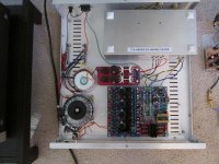
Here is my first Analogmetric dac. Much like the Mark II. The difference is this one now has OPA627AU SOIC I/V with 7th order GIC filter and AD8065 output buffer. I am listening to it now streaming Slacker radio. My headphone amp is based on the LME49710HA with BUF03 at a gain of 5. Metal can amp. 🙂 I am surprised how nice it is as a straight preamp. Using Paragon Regent loudspeakers with modified Sure 100 Watt class T amp on a decent linear supply. 😉 Dave
Here is my first Analogmetric dac. Much like the Mark II. The difference is this one now has OPA627AU SOIC I/V with 7th order GIC filter and AD8065 output buffer. I am listening to it now streaming Slacker radio. My headphone amp is based on the LME49710HA with BUF03 at a gain of 5. Metal can amp. 🙂 I am surprised how nice it is as a straight preamp. Using Paragon Regent loudspeakers with modified Sure 100 Watt class T amp on a decent linear supply. 😉 Dave
Attachments
Well!
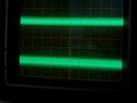
And this is what I see on the outputs of the TDA. I exchanged the IC whit other from my CDplayer. Changed all decouplings of this chanel. Changed the resistors, on the picture is 47 Ohms. Changed the place of resistor. The best result was, with cables from TDA pins and resistor on the next end where was the chinch.
This picture is with no signal from Spectralab, just connected. Resistors 47 ohms, are on traces from TDA outputs. The sensitivity of the oscilloscope is on 10mV. You can see the difference.
Did anybody measure the TDA1541 outputs of Analogmetric DAC?
On CD-pl. no such problems.
Attachments
Last edited:
Dac
Hi Stephan, No this isn't normal. What is your configuration? 8412 to TDA (NOS) or SAA7220 (OS) is in there? If one channel is normal and the other isn't. I'd wonder if your SAA7220 was bad. You may want to check your setup around the 8412. If you are using 8412 as master clock then with no input you should see no output on any channel. No input = no clock. If your using the retarded reclock of the original design you get a clock 100% of the time. Need some more information to help you. You mentioned using a chip from a player is it a plain TDA1541 or a TDA1541A? Are you missing the capacitor at pin 16-17? Dave 😕Well!
And this is what I see on the outputs of the TDA. I exchanged the IC whit other from my CDplayer. Changed all decouplings of this chanel. Changed the resistors, on the picture is 47 Ohms. Changed the place of resistor. The best result was, with cables from TDA pins and resistor on the next end where was the chinch.
This picture is with no signal from Spectralab, just connected. Resistors 47 ohms, are on traces from TDA outputs. The sensitivity of the oscilloscope is on 10mV. You can see the difference.
Did anybody measure the TDA1541 outputs of Analogmetric DAC?
On CD-pl. no such problems.
Hi David, yes, You are right, lack of information.
NOS, OS, doesn't matter. Picture is the same.
Both my TDA are the same, plan 1541. Capacitor is not missing 🙂
Yes, when SPDIF cable is not connected, the output lines are clean. The garbage comes when I connect the cable. I use no input transformer. Just 75 Ohm resistor and capacitors, like in Pedya Rogic DAC.
Something interesting. Today I soldered the screened wires at the output, on I/V resistors, and traces became clean, or much cleaner, then before, measured with probes straight on resistors.
OK, anyhow.
Today I did listen the voice of the DAC. OS. Honestly, I'm not impressed. Feel some lack of highs, lack of details. Something is, how to say, a little dark. I use a 18 ohms resistor, and tube output SRPP. Exchanged 2 brands of tube stages, nearly the same impression.
For good or for bad, I compare this DAC with Behringer Ultramach Pro - AK4394 DAC. Much more highs, details, impressions...And it is not moded, yet. May be, I'm not right to compare Delta-Sigma DAC with TDA1541?
Last edited:
Troubleshooting
Hi Stephan, OK, I see what your saying. It sounds like your coupling some trash into the analog side. I would use shielded cable from I/V to tube stage. There is usually a parallel capacitor across the I/V (or from grid to ground) where the current feeds the tube. If the original design called for 82 Ohm I/V, and you now have 18 Ohm I/V then scale the value of the capacitor. That is 4.5 times smaller value now. So that capacitor is now to large. I would start at 1n8 or 1800 pF measure the roll off with your scope using a 20 Khz tone from a test CD. Parallel or switch capacitors until you see some roll off in amplitude with 20 Khz. Sweep tones are useful here. My Analogmetric dacs are flat to 20 Khz. In truth I use my own analog circuits and not there's. I would consider moving the I/V resistors as close to the dac as you can and place the grid capacitor there too. Run screened or shielded cable to the grid of your tube stage. It could help if your star grounding as well. Many of my project start out on a piece of wood. You didn't send a picture so I don't know what your grounding scheme is. If your decoupling the TDA with capacitors with short paths to pin 5, then the noise should be small. Less noise pick up. It seems to me your just needing to do some fine tuning. As to Delta Sigma dacs, I have a 8416/8421/CS4398 with Lundahl transformers. I find my 2 TDA builds are better in the trebles with a smooth response and nice fast bass. My 4398 dac is stronger in the bass with slightly less defined trebles. A very smooth analog sound. I still like the delta sigma. I think there is more truth with the TDA's. I hope something here helps. Dave 😉Hi David, yes, You are right, lack of information.
NOS, OS, doesn't matter. Picture is the same.
Both my TDA are the same, plan 1541. Capacitor is not missing 🙂
Yes, when SPDIF cable is not connected, the output lines are clean. The garbage comes when I connect the cable. I use no input transformer. Just 75 Ohm resistor and capacitors, like in Pedya Rogic DAC.
Something interesting. Today I soldered the screened wires at the output, on I/V resistors, and traces became clean, or much cleaner, then before, measured with probes straight on resistors.
OK, anyhow.
Today I did listen the voice of the DAC. OS. Honestly, I'm not impressed. Feel some lack of highs, lack of details. Something is, how to say, a little dark. I use a 18 ohms resistor, and tube output SRPP. Exchanged 2 brands of tube stages, nearly the same impression.
For good or for bad, I compare this DAC with Behringer Ultramach Pro - AK4394 DAC. Much more highs, details, impressions...And it is not moded, yet. May be, I'm not right to compare Delta-Sigma DAC with TDA1541?
Thank You for support, David!
I don't use parallel capacitor across the I/V.
Watching the trace from tube on oscilloscope, it doesn't look dirty. Dirty looks trace from the DAC at very high resolution(10mV). Off course, if I have garbage, I amplify it wit tube. Do You think, it is the reason for lack of highs? I checked for roll off at 20K. There is no attenuation. Wonder, why then highs are weak?😕
Any way. Today I listen again. Exchanged the speakers and amps. The same impression.
Then, I began to increase the I/V resistor. Now is 33 ohms. I feel may be some improvement. Not sure. But tomorrow, I'm going to increase it more. Will see. And with capacitor, as You say.
Here you are the tube stage. I do not apply the filter. Just the 33 ohm resistor, close to TDA. And screened cables. The tube is with u33. Output capacitor is russian, military grade. I did hope, the problems come from it, but people here told me, that it is good, much better than WIMA MKS/MKP.
What to say? The sound is not bad. But I expected more.
Attachments
Treble....
Hi Stephan, So... The filter in the box on the schematic isn't used? OK. If your using NOS (non oversampling) then you have fewer samples and must use SineX/X compensation. Without compensation there will be progressively weaker trebles from 14 Khz and up. This is often done with an inductor. With OS (over sampling) the interpolation in the digital filter will create new samples and give flat response to 20 Khz. Yes... you can increase the I/V resistor. I use 39 Ohms in a tube/jfet SRPP. I can hear the THD increase and there is an odd surging with deep bass. I suspect that is the compliance being exceeded. It still sounded quite OK. 😉 I am being a little picky here. I hear the Russian capacitors are very good too. 😛 I will look at my notes and see on that inductor compensation. I do OS so far. My attempt at NOS didn't play. I will write more later. Dave 😎Thank You for support, David!
I don't use parallel capacitor across the I/V.
Watching the trace from tube on oscilloscope, it doesn't look dirty. Dirty looks trace from the DAC at very high resolution(10mV). Off course, if I have garbage, I amplify it wit tube. Do You think, it is the reason for lack of highs? I checked for roll off at 20K. There is no attenuation. Wonder, why then highs are weak?😕
Any way. Today I listen again. Exchanged the speakers and amps. The same impression.
Then, I began to increase the I/V resistor. Now is 33 ohms. I feel may be some improvement. Not sure. But tomorrow, I'm going to increase it more. Will see. And with capacitor, as You say.
Here you are the tube stage. I do not apply the filter. Just the 33 ohm resistor, close to TDA. And screened cables. The tube is with u33. Output capacitor is russian, military grade. I did hope, the problems come from it, but people here told me, that it is good, much better than WIMA MKS/MKP.
What to say? The sound is not bad. But I expected more.
Sine X/X compensation
http://www.diyaudio.com/forums/digi...220p-b-will-take-som-time-40.html#post2957130 Go back to this post. Here is a Sine X/X on the left side diagram. 😀
http://www.diyaudio.com/forums/digi...220p-b-will-take-som-time-40.html#post2957130 Go back to this post. Here is a Sine X/X on the left side diagram. 😀
OS
 They go quite low for 6.5" woofers..... I think you need to try a few things to get a handle on the issue. Dave 😉
Hi Stephan, OK, got it. I'd try a solid state I/V to see if that helps. I don't know if you have a gain issue or what... The schematic I pointed you to I did build and it is nice. Do you have good bass drive in your system? I suspect the Delta Sigma will have much stronger bass. I am currently using the Paragon Regents. For reasons I can't mention openly. They are transmission line bass with D' Appolitto woofer tweeter woofer with Dyna Audio drivers.For now, I use only OS.
Thanks!
They go quite low for 6.5" woofers..... I think you need to try a few things to get a handle on the issue. Dave 😉- Home
- Source & Line
- Digital Line Level
- DAC build TDA1541A/SAA7220P/B *will take som time*