If I want to add a LED for the power on indication, where to connect the LED with no affect the DAC
Ha Ha, never mind, I just ask if I can add another LED for this purpose.
no problem! all led for it!
red, green..
Do you test the sound?? how you think??
Thanks
Huh, I still waiting the 6H30pi-DR, and I know I will get them tomorrow, so I will test the DAC tomorrow, thanks!
I tested the DAC today, but something wrong, so bad only one channel work another one no sound come out!
I tested the DAC today, but something wrong, so bad only one channel work another one no sound come out!
check cs8414 and IV stage! And out put L change for R, when conect to IV stage
But I think I needed to change a 100VA transformer for the IV stage, 2A for filament is no enough, 3A or higher, cause when I plug in two 6H30PI, the filament voltage drop to 5.3V, and the relay also can't function correctly
enoughtBut I think I needed to change a 100VA transformer for the IV stage, 2A for filament is no enough, 3A or higher, cause when I plug in two 6H30PI, the filament voltage drop to 5.3V, and the relay also can't function correctly
1. transformer manufacturer in China so often, not in line with current practice!
I spend 3 times more power for incandescent,
2. You can reverse the wires to iv (R to L), to check the channel no sound, at the DAC to determine whether or IV!
R80-36
Well i wired the 260v supply only 2 green and 1 orange and my transformer got hotter and hotter giving off fumes ! result head hurts .Not sure what going wrong as for the heater wires i am confused which colours ,can someone confirm please
Well i wired the 260v supply only 2 green and 1 orange and my transformer got hotter and hotter giving off fumes ! result head hurts .Not sure what going wrong as for the heater wires i am confused which colours ,can someone confirm please
Well i wired the 260v supply only 2 green and 1 orange and my transformer got hotter and hotter giving off fumes ! result head hurts .Not sure what going wrong as for the heater wires i am confused which colours ,can someone confirm please
changed transformer to lesser power and same thing happens again ,transfo overheating smoke !
changed transformer to lesser power and same thing happens again ,transfo overheating smoke !
Just use one green (260v) and the orange(0v) for 260v. Do not use use two greens. Keep in mind the orange will be part of your ac voltage, so do not hook it to the ground (0) on the board, put it to the terminal marked AC. So a re-cap, one green to terminal marked AC, and the orange to the other terminal marked AC.
I would put a fuse on your primary side of your transformer for testing and for use, it will blow if you are shorting something out.
ben-jam-in thats great thank you ,
Not sure where i got the 3 wire idea from, now i think about it 2 makes sence.
After power up i get now +300v at sshv,i wish there was some basic instructions .
ben-jam-in would you offer help with heater wiring please i will never get it right thanks
regards john
Not sure where i got the 3 wire idea from, now i think about it 2 makes sence.
After power up i get now +300v at sshv,i wish there was some basic instructions .
ben-jam-in would you offer help with heater wiring please i will never get it right thanks
regards john
ben-jam-in thats great thank you ,
Not sure where i got the 3 wire idea from, now i think about it 2 makes sence.
After power up i get now +300v at sshv,i wish there was some basic instructions .
ben-jam-in would you offer help with heater wiring please i will never get it right thanks
regards john
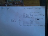
K, here is a pic that may help you. This is how I wired my R80-36 for the heaters.(8.15v) Our mains are 120v here and this being a 115v/230v winding I end up with a voltage higher than what the numbers say on the tranny. (There is also the option of getting 8.8v as well)
Keep in Mind you have 2 gray wires and 2 blue wires to choose from. you have to switch them around until you get the right voltage. When you are using the wrong ones you will notice your voltage is less than it should be, it will subtract. You will sort it out. Test the voltages first with a DMM before connecting them to the board of course.
Are you using Resistors as a test load for the SSHV board before you put the tubes in? You should test the filament heater circuit and the HV circuit seperatley before you stick the tubes in. Let us know if you have not done so, and do not power up the board yet.
Ben
Attachments
Ben
Keep in Mind you have 2 gray wires and 2 blue wires to choose from. you have to switch them around until you get the right voltage. When you are using the wrong ones you will notice your voltage is less than it should be, it will subtract. You will sort it out. Test the voltages first with a DMM before connecting them to the board of course.
Yes i worked that out the other day but could not get enough volts no matter what combo i used
Are you using Resistors as a test load for the SSHV board before you put the tubes in? You should test the filament heater circuit and the HV circuit seperatley before you stick the tubes in. Let us know if you have not done so, and do not power up the board yet
Ooops the tubes where in when i ajusted sshv to 300+ tubes are out now
Ok your pic was great i get 9.77volts
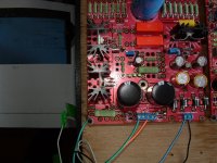
Ok pic shows all wires connected and tubes out ,i have not powered up or checked either sshv or heater ok
Thanks for time and trouble john
Keep in Mind you have 2 gray wires and 2 blue wires to choose from. you have to switch them around until you get the right voltage. When you are using the wrong ones you will notice your voltage is less than it should be, it will subtract. You will sort it out. Test the voltages first with a DMM before connecting them to the board of course.
Yes i worked that out the other day but could not get enough volts no matter what combo i used
Are you using Resistors as a test load for the SSHV board before you put the tubes in? You should test the filament heater circuit and the HV circuit seperatley before you stick the tubes in. Let us know if you have not done so, and do not power up the board yet
Ooops the tubes where in when i ajusted sshv to 300+ tubes are out now
Ok your pic was great i get 9.77volts
Ok pic shows all wires connected and tubes out ,i have not powered up or checked either sshv or heater ok
Thanks for time and trouble john
Attachments
My DAC ASH is all completed! Now enjoy the music...sound very good, compare to my DIY PCM63P-K*4 DAC, I found that the DAC ASH sound much more smooth and musical, I use 6H30Pi-DR in the IV output stage, it is a very good russian tube! With a lot of Hi-Fi parts like Kiwame resistors, Takman Carbon composit resistors, and Audionote's Tantalum resistors used as the IV resistor, Elna Silmic II, Panasonic FM, Mundof M-Lytic, Obbligato premium cap, etc, result is positive, no waste money in this DAC!
Attached some pics of my DAC
another view
Attached some pics of my DAC
An externally hosted image should be here but it was not working when we last tested it.
An externally hosted image should be here but it was not working when we last tested it.
another view
An externally hosted image should be here but it was not working when we last tested it.
lucylu
lucylu,
Let us do the heater circuit seperately from the HV circuit. So un-hook the HV supply from the board and cap off the wires for now.
If you have soldered a wire to connect the point marked +F to +6.3 undo it. (This jumper connects power from the heater power supply part of the circuit to the actual tube heaters and the relay) First you want to subsitute a load for the filament heaters, to check the circuit is working properly and adjust the voltage with the trim pot to 6.3v. When you have both the heating functioning and the HV circuit functioning you will connect +F to +6.3, and put the tubes in.
I am using the 6h30pi tubes. I connected 3, 1R2/10W resistors in series for a total of 3.6 ohms. Connect one end of the resistors to +F and the other to the point marked GND, on the tube side of the R32 resistor. This will substitute a load for testing. power it up and adjust the voltage to 6.3v. Be careful your load resistors may get hot, and be careful your LT1084 and heatsink may overheat. ( you mentioned your supply voltage was over 9v, check it again with the load, because it may be to high, the LT1084 will get very hot). Power it down and let it cool if things get hot between tests if you have to.
see post #1032 in the OLD THREAD DAC end. There is also a lot of other useful info in that thread.
Ben
After I shorted the jumper from 1-2 to 2-3, the problem fixed
I'm having similiar problems you were having. Maybe you can talk me through it. Also I don't know what you are jumpering. There is the three jumper between the I2S chip and 1865.
I put in all the new BL transistors and that fixed the problem. I have all the correct voltages at every chip pin.
When there was no RCA plug/input plugged into the SPDIF rca jack I would get the light near the receiver chip. I thought this was the lock light. When the I plugged in the rca the light would go out. I couldn't get any signal output from the board though.
I then pulled out the SC SPDIF transformer and put one in I know works fine. Now the LED near the receiver chip never comes on whether I have the rca plug in or out. Chips all have the right voltages. But I don't get any output.
I swapped in all the chips with new ones and others I know works.
I have no idea.
So I understand. That LED near the receiver is ONLY A TROUBLE LIGHT - correct?
Do I need to jumper something?
Correction - the jumper 1-3 are between the receiver and I2S chip. However on the schematic it shows between the other two chips. After reading it I understand I need to jumper something. I am running interstage transformers to the tube grid directly off the i/v transistors coming off the dac chip.
Should I make it 'in phase' pin 1 -2? Or out of phase 2-3? I understand it states for tube output out of phase is correct but with the old AN dac board which this is a copy there was no jumper so I imagine I was running in phase all these years?
Have people listened to the difference? How critical is the jumper wire material?
Last edited:
I'm having similiar problems you were having. Maybe you can talk me through it. Also I don't know what you are jumpering. There is the three jumper between the I2S chip and 1865.
I put in all the new BL transistors and that fixed the problem. I have all the correct voltages at every chip pin.
When there was no RCA plug/input plugged into the SPDIF rca jack I would get the light near the receiver chip. I thought this was the lock light. When the I plugged in the rca the light would go out. I couldn't get any signal output from the board though.
I then pulled out the SC SPDIF transformer and put one in I know works fine. Now the LED near the receiver chip never comes on whether I have the rca plug in or out. Chips all have the right voltages. But I don't get any output.
I swapped in all the chips with new ones and others I know works.
I have no idea.
So I understand. That LED near the receiver is ONLY A TROUBLE LIGHT - correct?
Do I need to jumper something?
I know that the LED beside the CS8414 is a error light, not a lock light, means if a correct SPDIF signal in the LED will off, if no, the LED light on so. I use all 2SK170BL too, no problem with the voltage came out!
I use the S22083 Digital trans, work fine, but actually I hear no difference between the S22083 and PE65612 or sumlink DV-709, I think a better trans maybe have a better noise floor.
I'm now shoted the jumper 1-2, no problem came out yet, I run the DAC around 10 hours, very stable. The jumper near the CS8414 is a phase control, shoted 1-2 is outphase, 2-3 is inphase, but I have no idea with this jumper function.
Phrarod, did your DAC work fine?
What kind of tubes you used?
I will try to jumper outphase I just wondered because I never ran across this.
I've been using the Audio Note Dac board for 7 years and just trying to perfect the power supply which is a mess on the AN kit Dac board.
This DAC END is a direct copy of the audio note board which is good for me because I love the sound of the Audio Note but know a better power supply would help it. Thus I built this one.
As far as I know the AN dac board doesn't swap the phase. I guess I will try it both ways and see. I hope this is the obvious simple solution. I feel stupid pulling our the Scientific Conversion SPDIF trans when the problem is obviously the fact there was no jumper.
Theorectically the best input trans would reduce jitter which is what we all are trying to do with digital. The lower the jitter the more expansive, natural and detailed the sound.
- Status
- Not open for further replies.
- Home
- More Vendors...
- Quanghao Audio Design
- DAC-ASH (dac-end 2 up date)