I'm officially part of the Miro DAC club! It's a Miro PCM63 board with the JLSounds usb interface. The I/V stage is AD797 opamps. The opamps have a separate 12v supply. The PSU is Miro's PSU-2 design, but I designed my own more-compact pcb version. I also included an output selector on the back of the DAC. Thanks to @miro1360 for the design and thanks to @zoom777 for selling me the nicely-built completed PCM63 board. It came together easily and I'm very happy with the results.


Folks,
Trying to get a new build to play music, which it does not yet. Miro AD1862 w/ JLSounds USB board.
PSU1 works, I can see 5V and 12V at the DAC PCB. Source is PC Windows 10. My first rodeo so not sure it's configured correctly but working on that. PC will play internet radio through MusicBee. I have downloaded the JLS driver from their site and can see that on the PC settings.
Photo of the board below. Caps, DACs and Opamps are oriented correctly. Looks like components are correct per post #1 Miro's blog detail.
With the USB cable inserted in the input, the adjacent LED does illuminate.
Any guidance on how to diagnose / getting it to play greatly appreciated in advance.
Got it running w/ Tan's help (zoom777). Thanks Tan! Missing two jumpers to power the JSL and re-downloaded the correct driver.
Jim
Jim
AD1865 build is up and running. Echoing @JKiriakis in thanking Tan for providing the dac board and for his guidance and support in putting it together. Going to run it in for a bit before seeing how it compares with the TDA1541A and AD1862 builds. Many thanks @miro1360 for your gifts to this community. I have 3 of your designs now!!

@carlman14 @JKiriakis @arteom ,
You guys are welcome. Glad you found success in Miro's fuss free designs which can be very satisfying.
You guys are welcome. Glad you found success in Miro's fuss free designs which can be very satisfying.
Hi AndyYes that's correct. I should have included the I/V resistor in the schematic. I have my tube stage in another box, exactly as the schematic, which I will link with a short connector. I was thinking of putting the I/V resistor in the box with the DAC in, on the DAC output pins. I may eventually put everything in one box but while I'm experimenting it's helpful to have modular units I can switch around. I've been listening to this ECC40 stage for a little while now as a line stage and I really like it a lot. Very curious to put it on the end of a DAC build.
View attachment 1391674
ECC40 is very good triode, and I think that can be sett slight advanced.
I made a spice model prety accurate.
Please take a look at the settings.
Your settings are too low with current and anode (Vak not Vb...) voltage
Also You can use negatv grid bias point of about -3.6V to have a chance to use battery (3 x 1.2V NiMh) or other close standard value different type battery.
OR stay with RC in cathode...
.
The better settings are dipely inside max values and adopted to 350V of Vb.
Other values can be read from graph.
Vin=0.25Vp-p
This is for Riv=125 ohm for Idac=2mAp-p.
for
Vout=2.1Vrms or 5.95Vp-p which i think is more than needed.
In general it is 120 ohm of standard value...
.
Output impedance is about 7260 ohm, which is good for tube next devices with big Rin values
But can be unsuficiant low for solid state succeding sections with lower input Rin...
A buffer can be welcome.
.
There is one thing left
To check with PSpice specific values of Ck.
I will send latter...
I am posting a spice model t+for ecc40
.
Code:
**********************************************
* Created on 12/11/2024 10:09 using paint_kit.jar 3.1
* www.dmitrynizh.com/tubeparams_image.htm
* Plate Curves image file:
* Data source link: philips datas
*----------------------------------------------------------------------------------
.SUBCKT ECC40 1 2 3 ; Plate Grid Cathode
+ PARAMS: CCG=2.8P  CGP=1.1P CCP=2.8P RGI=2000
+ MU=32.93 KG1=1201 KP=285 KVB=300 VCT=0.34 EX=1.4
*----------------------------------------------------------------------------------
* Vp_MAX=500 Ip_MAX=17.5 Vg_step=2 Vg_start=2 Vg_count=11
* Rp=22000 Vg_ac=0.125 P_max=1.5 Vg_qui=-4 Vp_qui=207
* X_MIN=83 Y_MIN=42 X_SIZE=838 Y_SIZE=590 FSZ_X=1749 FSZ_Y=741 XYGrid=true
* showLoadLine=y showIp=y isDHT=n isPP=n isAsymPP=n showDissipLimit=y
* showIg1=n gridLevel2=n isInputSnapped=n
* XYProjections=y harmonicPlot=y dissipPlot=y
*----------------------------------------------------------------------------------
E1 7 0 VALUE={V(1,3)/KP*LOG(1+EXP(KP*(1/MU+(VCT+V(2,3))/SQRT(KVB+V(1,3)*V(1,3)))))}
RE1 7 0 1G  ; TO AVOID FLOATING NODES
G1 1 3 VALUE={(PWR(V(7),EX)+PWRS(V(7),EX))/KG1}
RCP 1 3 1G   ; TO AVOID FLOATING NODES
C1 2 3 {CCG} ; CATHODE-GRID
C2 2 1 {CGP} ; GRID=PLATE
C3 1 3 {CCP} ; CATHODE-PLATE
D3 5 3 DX ; POSITIVE GRID CURRENT
R1 2 5 {RGI} ; POSITIVE GRID CURRENT
.MODEL DX D(IS=1N RS=1 CJO=10PF TT=1N)
.ENDS ECC40
*$
Last edited:
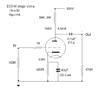
Hello Zoran. Thanks for your input and calculations. I think the ECC40 is worth some good input. So the schematic would look like the attached one. As you know, for a fixed B+ the anode resistor gets smaller as the current gets bigger. So for your operating point we have a 27K anode resistor instead of 47K. I have generally found that 5x the Rp of the tube gives the cleanest sound. As you can see, that reduces the current to around 3mA.
I can see benefits in more current and I can see benefits in a larger anode resistor. Choices! What do you think of meeting somewhere in the middle, like 4.5mA current? Note that my B+ is approximately 324V - this is my standard B+ PSU. A higher B+ is always nice but that would mean a new mains transformer. So that remains theoretical for those starting a build from scratch.
I can see benefits in more current and I can see benefits in a larger anode resistor. Choices! What do you think of meeting somewhere in the middle, like 4.5mA current? Note that my B+ is approximately 324V - this is my standard B+ PSU. A higher B+ is always nice but that would mean a new mains transformer. So that remains theoretical for those starting a build from scratch.
Attachments
The goal is to have as high Anode voltage as we can, no the high current by force, because the tuve is voltage dvice not current device as BJT...
.
And in the most linear region as we can. Because of minium THD. Load line is also in function of THD.
All that inside the borders of maximum values given by the manufacturer.
.
Yes it would be better with higher value of PS that You alredy have 324V.
But I can suggest to replace R with L in the power suply if the R component in RC filters exists?
With lower Rdc of L total Vb will be higher?
.
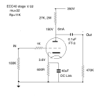
Here are optimum settings for 324V
THD=0.09%
Vin=0.25Vp-p Vout=2Vrms, Riv=125ohm for Io=2mAp-p
RL=22K
I will model the Ck value in pspice and post...
.

.
And in the most linear region as we can. Because of minium THD. Load line is also in function of THD.
All that inside the borders of maximum values given by the manufacturer.
.
Yes it would be better with higher value of PS that You alredy have 324V.
But I can suggest to replace R with L in the power suply if the R component in RC filters exists?
With lower Rdc of L total Vb will be higher?
.
Here are optimum settings for 324V
THD=0.09%
Vin=0.25Vp-p Vout=2Vrms, Riv=125ohm for Io=2mAp-p
RL=22K
I will model the Ck value in pspice and post...
.
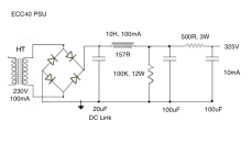
Hello Zoran. Here is my standard PSU. I use a 230:230V toroid and SIC 1200V diodes. There is not much voltage to be gained in the PSU. I think 22K anode load is too low for this tube. It may look good in theory. But I would have to listen to it - from experience of different values of anode load I would want it to be around 40K somewhere.
It would be possible to use a plate choke. I have a pair of amorphous ones, good quality, but I still prefer the sound with a resistor load so for me that stays. Others may want to use an active load or a plate choke, it would be their choice of course. I can only suggest what sounds best and most natural to my own ears, listening to acoustic instruments and voices. For sure, you can get good sounds out of an ECC40 so it's a tube worth looking at.
It would be possible to use a plate choke. I have a pair of amorphous ones, good quality, but I still prefer the sound with a resistor load so for me that stays. Others may want to use an active load or a plate choke, it would be their choice of course. I can only suggest what sounds best and most natural to my own ears, listening to acoustic instruments and voices. For sure, you can get good sounds out of an ECC40 so it's a tube worth looking at.
Attachments
Andy
There is no point in this case to exchange R of 500 ohm with say another L of 157ohm Rdc choke.
Because the volyage will be with 6mA consumption only 2V higher... Leave as it is.
But
Because of the solid state rectifier used,
You can increase first C of 20uF value, to 100-220uF.
To have better ac filtrtion?
.
In some cases that R bleader can make the sound somehow "compressed", try it without that R.
OR make some circuit with realy to close R in PS circuit to discharge Cs after power off?
.
There is some spice results for specific 324V Vb.
Very low THD 0.09% with 5.5Vp-p output and 125ohm Riv will be lower for lower values and lower output.
Output resistance is higher so the absoute minimum of R next input value is 220K for -025 db loss.
Any lower value will additionaly give limiter-compression effect in sound...
So for universal use, tube bufeer is the solution.
Value of Coutput is crucial to be higher for proper phase and response 2.2uF/250V is minimal value.
Type is from personal preferences...
2.2uF for 470K Rin next stage
4.7uF for 220K Rin minimun next stage
Values of Ck are critical too for the proper phase response, and they are from 100uF min to 470uF max.
Rgs can be even lower from 470 ohm to 1k max.
.


.
Very low THD 0.09% with 5.5Vp-p output and 125ohm Riv will be lower for lower values and lower output.
Output resistance is higher so the absoute minimum of R next input value is 220K for -025 db loss.
Any lower value will additionaly give limiter-compression effect in sound...
So for universal use, tube bufeer is the solution.
Value of Coutput is crucial to be higher for proper phase and response 2.2uF/250V is minimal value.
Type is from personal preferences...
2.2uF for 470K Rin next stage
4.7uF for 220K Rin minimun next stage
Values of Ck are critical too for the proper phase response, and they are from 100uF min to 470uF max.
Rgs can be even lower from 470 ohm to 1k max.
.
.
Hi Zoran. For the PSU I could increase the size of the first capacitor but it wouldn't make much difference to the output voltage. I like to have a DC Link as first cap because it sounds better than electrolytics. There's always a method in these choices!
The bleeder resistor is there for safety reasons as you know to discharge the B+ voltage. It's a simple way of doing it. I haven't tried more complex alternatives. I could try without it and see if I can hear any difference, that could be interesting, but I would put it back for safety reasons. Safety first.
Some other choices -
- 470R grid stopper would be fine
- I'm not too happy with 22K anode resistor, I would want it higher
- 100uF cathode bypass is OK, but my preferred capacitor is DC Link and that would be a big size. Electrolytics will sound worse than DC Link caps. I did a big bypass cap shootout and the only other choice that was nearly as good as DC Links was AudioNote Kaisei in parallel with Elna Silmic II, like 47uF + 47uF or 100uF + 100uF. That's another way to get higher values. But cathode bypass caps are quite audible and have to be chosen with care. So I stay with DC Link caps and use what I have. I have some 70uF ones but they were too tall for the case I used. After that they get expensive as well as big.
- This stage should go into a next stage of minimum 100K input resistor to ground. In that case 0.1uF is enough. Again, the quality of sound of the capacitor comes first. Coupling caps are very audible. I use FT-3 teflon caps. They are again large in size, so 0.22uF would be possible but not much more, and really 0.1uF is enough. Yet again, larger would not fit in the case and I would not use larger caps that were not teflon. I have tried 1uF KBG PIO Russian caps and though they are good they are not as good as FT-3. So I stay with teflon here.
- Yes, a buffer stage would be needed if feeding a solid state preamp, like a cathode follower. It would degrade the sound but it would be a choice. I have a valve stage so 100K input works fine.
Last edited:
@mz543578854
"While I agree that Andy has provided his tube I/V suggestions without setting them in proper context / showing how exactly he would use them, and did not explain e.g. that the 100k he has / keeps in it, because for him it is a building block he wants to be able to test isolated, there is no need to get rude."
I answer to your comment about me and your rudiness charge about the behavior you attribute to me, as it seems to a lesson given to me and a try to change the history, then maybe influence mods reactions on agenda? It worked once, bravo !
First, noone cares about such inputs. Then to detail :
That's your thinking MZxxxxx , but I was not rude, my "said" rudiness you attribute to me was answering to the one of Andy (he shooted the first while I helped from several PM he asked and others threads.). And then tried to discharge himself of such by flooding the fisch talking about passive parts which was not the subject of my answer but his odd shematic, we talked a lot already in that thread and doesn't look like it should, that's all.
You have missread and avoided totally that, the context, and for the second time you pursue with your moralistic comments (that was erased by a mod once) with a great care to paste only the citations w/o the context. Well done but that is totally dishonest. Try to input to help others not to critic the ones you don't like. Andy focused on passive components to discharge himself after from his rude commments I was not happy about (and that makes sense)
I certainly not diserved such "cheat" nore his rude answer, nore your moralistic coment on agenda. That's all and not your business. If you have readed this thread you will see I have helped here a lot and also given concrete things. What about you ? Only morals lessons ? Btw if you have readed with honnesty you would have understand I copied those links from Miro blog thread and it was about to help again on the paper from T Loersch (firrt link). I just drag and drop. So critic Miro1360 if not happy of what he has done gently for others and the linkk he provides.
Okay, please ignore me or put me in your BL, it will help to not pollute the thread with your not justified attack against me and the answer it calls for your agenda. Your behavior is the one of the mods you attribute to yourself. I only react cause your input is once again a try to dirt me (for the second time), which is unfair and odd due to your weak help for others. Again, be rude for others phrased gently is not a prove of educated and civilisated behavior, don't be surprise people, like I, reacts so. And following like you do to lapidate in group, well a very uncivilisated behavior, not to say unclever and a sad group behavior.
So sorry no lesson to recieve from you. And sorry for others, but it is not in my habits to be trolled, pointed out, and not reacting. I try now to avoid that thread as now the people who want to be helped are very sensible and even don't understand for most, english is not the mother language of everyone (illiterate would say a fool) , which ask twice efforts for some when they want to help. Andy answered himself and doesn't need you btw for that.
Best.
PS : mods, feel free to sin bin me, like what you did already, because I simply reacted to trolling and "polished sad attacks" (named condescending in good english if words make sense).
This place is becomming unfair and wokised if we should help others and being wounded for that because they are not happy to progress. Sorry again to defend myself.
Last edited:
@diyiggy Neither do I have an "agenda" nor have I "cheated" (if that completely weird accusation was to me). The problem is that you are not able to communicate in a civilized manner.
If you dump your impolite, accusative content into an otherwise great to read thread, it of course is everyone's business to call that out.
If you dump your impolite, accusative content into an otherwise great to read thread, it of course is everyone's business to call that out.
Thanks, it is just I sincerely found your answer to me a little rude and unfair. Certainly my non ruled english or education. But problem is over as finally all is clear now.
I follow your tube adventure with great interrest. Frankly I was not trying to say to you which tube is better, etc. You know better than I here.
I follow your tube adventure with great interrest. Frankly I was not trying to say to you which tube is better, etc. You know better than I here.
Can I ask you what is a DC Link capacitor. I found a number of articles on the topic, similar to this one https://www.electrocube.com/pages/how-to-select-dc-link-capacitor-technical-bulletin. So in this context, does it mean film capacitor?Hi Zoran. For the PSU I could increase the size of the first capacitor but it wouldn't make much difference to the output voltage. I like to have a DC Link as first cap because it sounds better than electrolytics. There's always a method in these choices!
The bleeder resistor is there for safety reasons as you know to discharge the B+ voltage. It's a simple way of doing it. I haven't tried more complex alternatives. I could try without it and see if I can hear any difference, that could be interesting, but I would put it back for safety reasons. Safety first.
Some other choices -
I have made all these choices by listening to the alternatives and doing a lot of A-B tests. But your simulations are very valuable and constructive - many thanks for taking time for this. Your 120R I/V value looks good.
- 470R grid stopper would be fine
- I'm not too happy with 22K anode resistor, I would want it higher
- 100uF cathode bypass is OK, but my preferred capacitor is DC Link and that would be a big size. Electrolytics will sound worse than DC Link caps. I did a big bypass cap shootout and the only other choice that was nearly as good as DC Links was AudioNote Kaisei in parallel with Elna Silmic II, like 47uF + 47uF or 100uF + 100uF. That's another way to get higher values. But cathode bypass caps are quite audible and have to be chosen with care. So I stay with DC Link caps and use what I have. I have some 70uF ones but they were too tall for the case I used. After that they get expensive as well as big.
- This stage should go into a next stage of minimum 100K input resistor to ground. In that case 0.1uF is enough. Again, the quality of sound of the capacitor comes first. Coupling caps are very audible. I use FT-3 teflon caps. They are again large in size, so 0.22uF would be possible but not much more, and really 0.1uF is enough. Yet again, larger would not fit in the case and I would not use larger caps that were not teflon. I have tried 1uF KBG PIO Russian caps and though they are good they are not as good as FT-3. So I stay with teflon here.
- Yes, a buffer stage would be needed if feeding a solid state preamp, like a cathode follower. It would degrade the sound but it would be a choice. I have a valve stage so 100K input works fine.
DC Link - Polypropylene caps, high quality. Kemet is cheaper than Vishay but both good.
https://uk.rs-online.com/web/p/film-capacitors/1744358P?gb=s
https://uk.rs-online.com/web/p/film-capacitors/1744358P?gb=s
That's automotive polypro stacked foils caps with 4 poles leads most of the time. Panasonic made very inexpensive and neutral as well, good enough in serie in loyudspeaker filter too according the loudspeaker filter area..
Dunno for cathode bypass though (not needed maybe here in I/V conf as the I/V resistor before must be bypassed anyway before the serie grid resistor. A non metalized PP or a tin foil styrene is a good bet here. TMMV of course. You just want a simple resistor here and nothing else for a linear volt to current between grid and cathode ? Well it is above of my head.
As well Torsten Loesch nowadays would use more HF tubes he said (for evident reasons in this DAC I/V task imho as far I understood as we need some bandwidth in this digit to analogue task) , 5670 , 6AK5 for the I/V node as illustration. He imputed about that in the long TDA1541A thread.
Hope that helps.
used them in my SE 300b build, as cathode bypass and with the first inductor in the PS. The improvement in the bass region was remarkable.
- Home
- Source & Line
- Digital Line Level
- DAC AD1862: Almost THT, I2S input, NOS, R-2R