Sorry that my phone doesn't have good camera.
This is new version of Trop-001 schematic posted below.
Not sure if Google translate work well.
"Two years have passed since the publication of the TROP-001 discrete op-amp in Transistor Technology magazine in the spring of 2016. In the meantime, the TROP-006MF was developed to improve upon the compromises and things that were not possible with the TROP-001. There are two major differences from the TROP-001: the differential input stage is now FET, and the output stage has a new circuit. The TROP-001 was a combination of the TROTA-01 OTA circuit board and the TRBA-01 output buffer circuit board, but the TROP-006MF is composed of the evolved TROTA-02b and TRBA-02c. First, let me explain the difference between the TROTA-01 and TROTA-02b. The major difference is that the input differential pair has been changed from bipolar transistors to unipolar transistors. By using junction FETs, it can be used in a wider range of application circuits without worrying about input bias current. In addition, in the present day, when bipolar transistors specialized for low noise are almost nonexistent, the noise performance of the TROP-001 had to rely on the capabilities of the transistors used, but the 2SK3320 used this time has guaranteed noise characteristics and reduces mass production variations. In addition, by reviewing the circuit constants, we have improved the wide range of operating power supply voltages and the response characteristics at the time of excessive input. The paired output stage TRBA-02c uses a newly developed circuit, not an extension of the TRBA-01 circuit. In the TRBA-01, a complementary circuit using Nch and Pch junction FETs was used for the input stage, but due to the poor availability of PchFETs and the fact that the idling current of the output stage is affected by the characteristics of this FET input stage, the input stage of the TRBA-02c uses a single FET, and the circuit configuration is such that the variation in the characteristics of this FET does not affect the output stage. The reason for using a MOSFET for this FET is to reduce the DC potential level difference between the input and output. Furthermore, by applying a cascode bootstrap to this MOSFET with a transistor, the nonlinear change in input impedance with respect to changes in input voltage is suppressed, and the T.H.D. at 20kHz is improved by more than 6dB compared to the TROP-001 at large amplitudes. The mass production variation of the bias current of the output stage has also been improved by more than 10dB compared to TRBA-01, so you no longer have to worry about differences in characteristics when using multi-channels.
The low-load drive capability inherited from TROP-001 can directly drive low-impedance headphones with low distortion, so there is no need for a monolithic op-amp + transistor buffer configuration.
In terms of electrical specifications, it does not support rail-to-rail voltage output, which is common in monolithic op-amps, but its electrical characteristics, such as symmetrical clipping characteristics and low-frequency amplification, are comparable to those of high-performance audio op-amps, while also being as easy to use as a 4558-type op-amp.
As for sound quality, I think you will be able to fully feel the difference that is generally said to be between monolithic circuits and discrete circuits, so I hope you will give it a try."
Attachments

Are you sure it is 2200nF c0g dielectric? Probably x7r. 220nF typo?caps are 2200nF C0G/NP0
problem with the 1641 is its a little low current, one can use the quad version as some did in Diyaudio for that task. It will be a more fair way to compare both.
op828 is certainly below 2K hz the les noisy of all, but the i/v parts values of Cf and Rf has to be found, the rolling of opamaps w/o adjudting them is useless or at least not precise enough , then you can loose all the attributes of some op amps. I find it has a very analog character but not the pratt of the 1655/56 in the low dpt. At least in a drop replacment rolling game with same parts values around.
@tamra : nice to see exotic opamps 🙂 at least seen from my part of the world ! I wish I hhave easy acess to Akihabara stores 🙂 (I love your city)!
@diyiggy
It's sad that Japanese parts and shops are getting dissapeared.
Shop owner said that people can't even walk into crowded small path for small shops in 70's-80's.I wish I was there.
Still some tube amp and transformer shops are surviving.
I am not big tube fan or ignorant though.
That discrete opamp is not that expensive like stacattto or sparkos,may be for currency rate.
But Antek transformer or Hifi2000 heatsink case are expensive for shipping and tax.
I can say that food is definitely good,not expensive and sophisticated if not vegan.
It's good to visit here sometimes.
Yeah the world is changing, and too fast to my tatses !
My last time in Japan was a 4 weeks bag pack in march 2012 before the busy golden week. Tokyo to Hiroshima via Shikoku, of course Kyoto Nara, the main historical places/town... I wisch I had more monney to go there more often. Ahaha I bougth some good Oyaide Across 750 interconnects and linear bulky one for the main of my amp ! 🙂
I had the luck to spend one week in a japonese family (Kono) living in close suburb of central Tokyo (so still Tokyo), thanks to a friend that spoused their lovely daugther. She made 3 lovely children together that speak perfectly both japanese, english and french 🙂 having spent their childrenhood in those countries and thanks to their parents of course (the mother never succedeed to talk frenchbut has a goodd english).
Hey I wish I had enough monney to buy an old house in the center of Honshu or more in the south, seems some natives aging want to go in town.
But because the monney, also my little average brain, there is no way I speak japanese or good english one day, lol !
Last edited:
Pin 13 without the DAC chip is not connected anywhere. It is some residual voltage in the capacitors. Turn off the power supply, discharge both 47uF with a resistor, say 100ohm, and measure again. According to the schematic, you don't even have to turn on the power supply, it's all the same, the positives of the capacitor are not connected anywhere until the AD1862 arrives.
Right channel not working ☹️Hi guys
I finally built AD1862 , before put the ic on board test the voltage on all pin .
Everything ok , but voltage on pin 13 for right and Left channel is different.
Right channel is 1v
Left channel is - 6.7 mV
It is ok ?
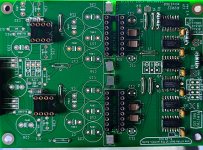
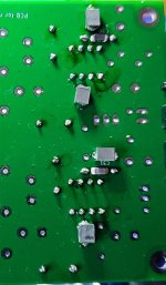
Good choice for decoupling around PCM1702 and good idea for soldering them. For decoupling for + and - you can freely use OS-CON and for the other three electrolytes it is important that they have low leakage current.Got started on the PCM1702 build today. The SMD caps are 2200nF C0G/NP0 and 100nF 2% 50V PPS. Both are 1812 size.
The 1206 are 47pF C0G/NP0.
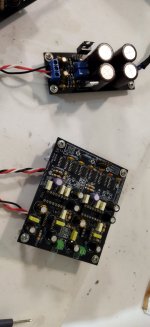
I'll use a separate supply for the opamp section.
Good luck with further work and for I/V you must use AD811, don't mess around with other op amps, there is no point.
Yes,I am native Japanese.Are you native ?
He has to go through the way of the Cross, first, and his calvary to find the Grail, don't serve him on a silver plate 😀Good luck with further work and for I/V you must use AD811, don't mess around with other op amps, there is no point.
too easy otherwise 😀😀😀😛
Thank you 🙂Good choice for decoupling around PCM1702 and good idea for soldering them. For decoupling for + and - you can freely use OS-CON and for the other three electrolytes it is important that they have low leakage current.
Good luck with further work and for I/V you must use AD811, don't mess around with other op amps, there is no point.
The 1812 C0G NP0'S are 220nF/50V, not 2200nF😅, my bad it was a typo.
I've got several Sanyo caps, OS-CON only 4*220uF/10V...the rest are 22uF/25V or lower capacitance. Sanyo SEPC I have several 270uF/16V.
You think any of those are better than the Nichicon FG currently populated?
I found 1812 size SMD's are the perfect with for 5mm pitch TH film caps.
As I had 30 or more of the PPS caps and about the same of the 220nF C0G NP0'S and no suitable TH film caps...I went with the SMD's 🙂
- Home
- Source & Line
- Digital Line Level
- DAC AD1862: Almost THT, I2S input, NOS, R-2R