Even the operating system has its own sound. That's why I made my own Linux. 😎I have never had or made a device in my life that has no effect on the sound.
Last edited:

Don't forget to cut the external PSU jumper (page 4 of the JLS instructions). This is a must if you are adding a separate power supply for the XMOS part. You can damage the USB port on your PC. Cut as shown (red line) and check if it is separated.Roger that, thanks for the help
Thanks for that Nixie62, I will file that in my "important things to do list". I am still searching for a suitable AC-DC power supply circuit that will work. Most circuits assume a DC-DC type circuit using a wall wart as a power supply and just adjusting for Vout. Hard to find one that shows the rectifying front end and the step down voltage part. I was thinking of maybe purchasing a couple of the adjustable supplys I have seen online.
Regards
MM
Regards
MM
I’m building up another miro dac (1862) and see the original i2soverusb pcb offered by jlsounds is out of stock. Is their other i2soverusb with isolated outputs pcb a suitable replacement? If so, what if any changes would be necessary? I’ve reached out to lyuben at jlsounds.
Thanks
Thanks
It is a better replacement yes. It's fully compatible, already tested. No configuration changes, datasheet remained the same.
AD811 or slightly worse OPA861 , I/V with AD811 was made by @Vunce and @zoom777, it is best to read their posts about the resultsNo, we haven't tried CFA op amp, any recommendations?
I also preferred the sound of tubes in my DAC for a long time, just like you. And very simple solutions with tubes can sound much better than a good VCF op amp, they have that something in the sound that attracts regardless of whether it's a passive I/V .I agree, but I personally like the sound of tube. Good passive I/V is good pasiv I/V. We tried a hand-wound non-inductive resistor and a transformer I/V. Like ANK kits.
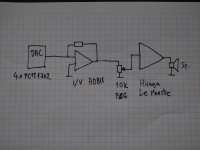
Honestly, I have never connected a DAC only with passive I/V(resistor, transformer), I always wanted my DAC to be able to drive an any amp in any conditions, which means low output impedance and high output voltage. In digital production, I consider a preamp unnecessary in the system, a link that subsequently degrades the sound. This is also the role of I/V itself.
That's why I intentionally sketched the sound path in my system, there are no capacitors, resistors, transformers, additional gain stages, output directly from AD811 to the 10k P&G slide pot and then to Le Monstre.
Maybe I'm wrong, but all my friends who have heard the sound at my place take it as a reference that they can't really capture, no matter how much they invest in their equipment.
I recommend that you try it as soon as possible, the difference is like night and day. A completely different sound image. Honestly, you need to find suitable tubes the scheme is no longer simple, but the result is far better than with classic solutions with tubes. Otherwise, as soon as we use tubes, we have to be prepared that we have a capacitors(or transformer) in the signal path, but in this case with grounded grid they play a small role in the overall sound.We haven't tried this. Maybe someday. Honestly, we chose classic amplification because it avoids capacitors in the signal path. We also tried with a capacitor at the output, but then it colors the sound.
Just like the resistor in the cathode, it is the tube that takes over the complete amplification and has the greatest influence on the sound itself. The cathode resistor would have to be below twenty ohms. The input impedance is even lower than the cathode resistor, which puts the DAC itself in a more favorable position than passive I/V and the tube behind it.
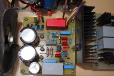
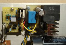
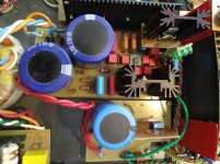
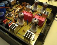
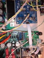
I forgot to write that most people are concerned about capacitors, resistors, transformers, op amps, tubes and their influence on the sound but the biggest advances and improvements can be achieved already on the power supplies be it LV or HV. Not much attention is paid to this and with a sound source such as a DAC it really plays a role. In the pictures are my HV regulators that I used in my DAC and hybrid amplifier. And a picture of the first grounded grid I/V stage with 6S4P.
Attachments
Last edited:
Good stuff .. I am going to 'steal' the AD1862 board design and the PSU design to replace the AD1865 board in my ANK L4.1 DAC.
That way it looks like the standard I2S between the SAA7220 and CPLD. Considering the SAA7220 as any I2S source. You can try to use the code for CPLD directly without change.@miro1360
you're right. Therefore, I would like to continue using this trigger type of code.
In any case, wouldn't it be advantageous to have a higher oscillator frequency as much as the CPLD specs allow?
How do I fix it with OS version?
View attachment 1269787
View attachment 1269786
I just want to do this...
It doesn't matter if it's not master clocking
Give us some tested GG scheme for I/V. There is anything and everything on the net, I don't know what specifically to watch?Honestly, you need to find suitable tubes the scheme is no longer simple, but the result is far better than with classic solutions with tubes.
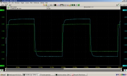
For those of you who use SPDIF/TOSLINK cards with the AK4113/4118, see below what is on the I2S output to the DAC. There are resistors 330-470ohm. It's too much and doesn't affect the sound well. That was taken off and jumpers were put on. R7, R8 and R9 should be bridged for Miro & Pavouk DACs with I2S inputs (LRCK, DATA & BCK). It works without error (tested at 384kHz SR) and the sound is cleaner.
Attachments

And something else about these AK4113/4118 boards. When you buy, make sure to buy one with an LCD display if that's what you want. I bought the PCB without the display because I have a few, and it turns out it won't work with the LCD display. The default variant is only for the OLED display or for the LED input indication (it always works). Of course, I got a OLED afterwards, but that one is a bit small for my needs. And SPDIF/TOSLINK is written in Chinese. I2S spells it right. 🤣
Attachments
@marcomariutto Miro's 1862 board was a significant improvement over the ANK digital board/setup. Of course, I went from spdif input to USB by JLsounds, and to powering the digital board by two Salas shunts. The DAC also had upgraded IV transformers in place. Don't want to derail this thread so feel free to PM me for more details.
I'm thinking about adding the option of spdif input to one of my MiroDacs. As I look around there are a few chips used for spdif to I2S conversion. What boards have you Fellas been satisfied with?
Nixie62, have you tried other converters and prefer this one based on AK4113/4118?
Nixie62, have you tried other converters and prefer this one based on AK4113/4118?
I have WM8804 in DDDAC. I don't know what the difference is. Take the AK4118 and remove the resistors from I2S. I have seen other PCBs with AK4118, they have remote control, display, SPDIF, TOSLINK, I2S, AES inputs and I2S output. And the Amanero copy can just be stuck from above.
https://www.ebay.com/itm/314963392048
https://www.ebay.com/itm/314963392048
Last edited:
Much has been said about the BJT IV from Sergio :
https://www.diyaudio.com/community/threads/dac-i-v-measurements.395738/
https://www.diyaudio.com/community/...-with-very-low-distortion.217459/post-5756616
Knowing Sergio's competence in audio circuit design, I also want to find out.
Although the power supply voltage is not listed in the original schematics, those skilled in the art can figure out that it should be +/-20~24V to have good performance.
Scaling down to +/12~15V rails plus 2.8k Riv, and the distortion figures look rather different in simulations.
But simulation is not reality, so there is only one way to find out.
The prototype works first time as expected, with 12V rails.
So direct plug-in to replace opamp IV (MUST remove Riv and Civ first).
DC drift from cold to steady state in less than 3 minutes is a not-too-small 60mV.
But once stable, it stays well within +/-5mV.
All transistors are matched in this case.
This will now go to Ireland for comparative measurements, as well as listening.
When all is fine, and there is serious interest, we shall publish Gerber.
Patrick
.
Attachments

- Home
- Source & Line
- Digital Line Level
- DAC AD1862: Almost THT, I2S input, NOS, R-2R