
I was ordered another spdif board - Dir9001. I hope to use together with Jlsound but that's later. I want to see how it works first.And something else about these AK4113/4118 boards.
https://ae04.alicdn.com/kf/Sb0a6913f448f4206a22389e62cc46f8d1.jpg
What kind the impressions of AK1113 board?
Has anyone used LT3045 (Ultrahigh PSRR linear low-noise regulator) or something like... instead MC78/79? Is there a reason to use discrete regulator?
Last edited:
I used the CS8414/16 for years, so during the corona crisis I switched to the DIR9001 because of less jitter, and you can really hear the difference. I haven't tried WM8804 but according to jitter it should be similar to DIR9001 while there is no jitter data for AK4113/4118.
The power supply-regulators is very important in this case, unfortunately I was not satisfied with the offered ready-made ebay solutions and I made my own PCB which unfortunately remained on the prototype version. I used three ADP7118 regulators in the first version to later replace two ADP7118 with Walt Jung 3.3V shunt regulators for the analog and digital sections of the DIR9001. The input receiver itself has its own ADP7118 and the DIR9001 PCB has its own transformer. I also added a 74HCT541 buffer to the DIR9001 output.
And I am happy with the result especially after installing the Walt Jung shunt regulator 🙂
Attachments

Better regulators should improve the sound(less jitter), but it makes no sense if the digital and analog sections don't have separate regulators, and that's the most important thing. A good discrete regulator(only shunt) can be better than the LT3042/45 or ADM7150 but there are very few of them and they don't exist in the ready-made version.Has anyone used LT3045 (Ultrahigh PSRR linear low-noise regulator) or something like... instead MC78/79? Is there a reason to use discrete regulator?
DIR9001, WM8804, WM8805 (jitter 50ms for all) .... AK4113/4118 (jitter 100ms) ... all of them are suitable for R-2R ... the winner should be the one that is more accessible to you (financially and technologically more friendly by connection or whatevery you are planing to do) 😊
"only shunt" What about the WJ superreg with sense and fast op amp. Should also be better than lt3042 or not?Better regulators should improve the sound(less jitter), but it makes no sense if the digital and analog sections don't have separate regulators, and that's the most important thing. A good discrete regulator(only shunt) can be better than the LT3042/45 or ADM7150 but there are very few of them and they don't exist in the ready-made version.
I was already buyed instead positive MC 7805 and 7812 - LM 2940T(5 and 12V). This is LDO stabs. I want to use for opamps and USB (galvanic isolation). I plan to get some discrete ones to try out - I'll check where I can get them.
If we are talking about digital circuits, in my tests and comparisons that I did more than ten years ago the shunt was always better than the series regulator, including the WJ superreg. Shunt has better performances in HF which are most important in the DAC itself. WJ superreg is certainly better than the LT3042/45, but the distance of the regulator, the length of the wires also play a role here, why a fast op amp if there is 10-15 cm of wire between the regulator and for example the DIR9001. It makes no sense for HF. The LT3042/45 themselves are meant to stand as close as possible to the load itself but it might be worthwhile to put a WJ superreg in front of them."only shunt" What about the WJ superreg with sense and fast op amp. Should also be better than lt3042 or not?
btw; In the WJ shunt reg from my picture are ADA4897 ( 230MHz, 120 V/μs, 1 nV/√Hz) which work without any problems but I am not sure that the classic WJ superreg would work well with it.
@Kokanee recently asked about a possible standalone 2x Single Rail power supply to supply 5V @400mA and 5V@100mA for the I2S board. I have 2 "FlexReg" boards I make that look like a good jumping-off point for a purpose-built board.
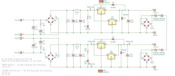
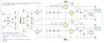
I sketched up a version with an on-board transformer (60x60 Amgis or Talema 15 or 25VA), and a separate version that can be used to hook up an existing transformer. I understand quite a few folks are using R-Core transformers with multiple secondaries, so the more compact board may be more attractive.
This is set up for FIXED regulators with pinouts like 7805 (Vin, Gnd, Vout) and LT108x-5.0 (Gnd, Vout, Vin). I didn't look at every possible regulator and associated pinout, so there may be other options that drop right into one side or the other of the heatsink if the pinouts match.
Here's a summary of what's going on for each PCB.
WITH TRANSFORMER:
PCB Dimensions: 100x130mm
Mounting holes on 10x10mm grid for easy modushop bottom plate mounting.
Includes AC Cap at input.
Configurable for 120V/240V
Use a 60x60mm Amgis or Talema 15 or 25VA transformer OR hook up to external transformer secondary connections
Includes rectifier snubbers (Optional - use Quasimodo to measure transformer)
Uses bridge rectifiers (easy install)
CRCRC pre-filter stage before regulators (18mm / 7.5mm LS caps)
FLEXIBLE to use either 7805 regulators OR LT1085-5.0 fixed regulators
PCB mount heatsinks. Of course smaller bolt on ones can be used for lower current.
1,000uF cap at the output
Each rail has a diode bridge as ground break to chassis ground.
LED indicator for each power rail
Bleeder resistor for each power rail
Connectors can accommodate soldering in wire (old school), Quick Disconnect spades, OR terminal blocks with 5/5.08mm lead spacing
WITHOUT TRANSFORMER:
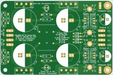
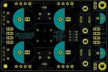
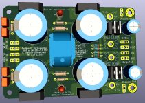
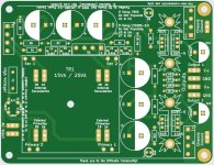
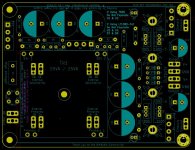
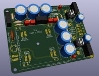
PCB Dimensions: 80x120mm
Connections to hook up to external transformer secondary connections
CLC pre-filter stage before regulators (Caps can be up to 25mm / 10mm LS or 18mm / 7.5mm LS caps)
The rest is the same as above - except for the AC bits that are missing.
Any interest in these?
I'll take comments and I'm willing to make some minor edits to one or both of these PCB's. I'll post Gerbers if there is interest.
I sketched up a version with an on-board transformer (60x60 Amgis or Talema 15 or 25VA), and a separate version that can be used to hook up an existing transformer. I understand quite a few folks are using R-Core transformers with multiple secondaries, so the more compact board may be more attractive.
This is set up for FIXED regulators with pinouts like 7805 (Vin, Gnd, Vout) and LT108x-5.0 (Gnd, Vout, Vin). I didn't look at every possible regulator and associated pinout, so there may be other options that drop right into one side or the other of the heatsink if the pinouts match.
Here's a summary of what's going on for each PCB.
WITH TRANSFORMER:
PCB Dimensions: 100x130mm
Mounting holes on 10x10mm grid for easy modushop bottom plate mounting.
Includes AC Cap at input.
Configurable for 120V/240V
Use a 60x60mm Amgis or Talema 15 or 25VA transformer OR hook up to external transformer secondary connections
Includes rectifier snubbers (Optional - use Quasimodo to measure transformer)
Uses bridge rectifiers (easy install)
CRCRC pre-filter stage before regulators (18mm / 7.5mm LS caps)
FLEXIBLE to use either 7805 regulators OR LT1085-5.0 fixed regulators
PCB mount heatsinks. Of course smaller bolt on ones can be used for lower current.
1,000uF cap at the output
Each rail has a diode bridge as ground break to chassis ground.
LED indicator for each power rail
Bleeder resistor for each power rail
Connectors can accommodate soldering in wire (old school), Quick Disconnect spades, OR terminal blocks with 5/5.08mm lead spacing
WITHOUT TRANSFORMER:
PCB Dimensions: 80x120mm
Connections to hook up to external transformer secondary connections
CLC pre-filter stage before regulators (Caps can be up to 25mm / 10mm LS or 18mm / 7.5mm LS caps)
The rest is the same as above - except for the AC bits that are missing.
Any interest in these?
I'll take comments and I'm willing to make some minor edits to one or both of these PCB's. I'll post Gerbers if there is interest.
Attachments
-
 FL2x5V_v1.0b_NoTrans_Schem.JPG103.3 KB · Views: 237
 -
 FL2x5V_NoTrans_PCB2.JPG118.8 KB · Views: 216
 -
 FL2x5V_NoTrans_PCB.JPG176.8 KB · Views: 189
 -
 FL2x5V_NoTrans_3D.JPG152.1 KB · Views: 211
 -
 FL2x5V_WithTrans_V1.0a_Schem.JPG131.2 KB · Views: 219
 -
 FL2x5V_WithTrans_PCB2.JPG117.6 KB · Views: 199
 -
 FL2x5V_WithTrans_PCB.JPG146.3 KB · Views: 191
 -
 FL2x5V_WithTrans_3D.JPG115.1 KB · Views: 231
Last edited:
Super cool Randy!
Even equipped with ground loop breakers 😉.
Will the skinny heatsink handle the higher current if used to power the USB side of the JLSounds board?
Maybe add vent holes in the pcb around the heatsinks.
Even equipped with ground loop breakers 😉.
Will the skinny heatsink handle the higher current if used to power the USB side of the JLSounds board?
Maybe add vent holes in the pcb around the heatsinks.
Let's do some math.
I think folks are running R-Cores with 9V secondaries. Let's assume a factor of 1.4x for voltage at the cap bank, so 12.6V before the regs. 5V after regs. 7.6V drop at the reg and 400mA draw.
P = I * V = .4A x 7.6V = 3.04W
Let me check heatsink specs....
These are the footprint currently on the PCB
1" Tall 13.4°C/W p/n 531002B02500G 40°C over ambient - TOO HOT
1.5" Tall 11.00°C/W p/n 513102B02500G 33°C over ambient - Pretty hot. Too hot?
I could go for a larger footprint heatsink:
1" Tall 5.50°C/W p/n 529702B02500G - Much better
1.5" Tall 3.70°C/W p/n 529802B02500G - Better yet
Last edited:
That works, and like you mentioned a taller sink can be used.
This board will be handy for the DIY'ers toolbox.

Edit: Datasheet states 13.4ºC/W?? That would be 40ºC above ambient.
This board will be handy for the DIY'ers toolbox.
Edit: Datasheet states 13.4ºC/W?? That would be 40ºC above ambient.
Last edited:
529802B02500G is definitely better, especially with holes underneath.
The board will grow a bit, but IMO it's worth it.
The board will grow a bit, but IMO it's worth it.
Randy, really nice work on both these boards, really glad to see the non transformer board. Now I can order that r-core that Vunce suggested with the 4 secondaries. 😉. Vunce, nice tweak about the extra HS holes if it can be done, even with the taller HS. It has been quite some time since I had to order pcb's from a pcb house. I will be ready for gerbers when the boards are ready.
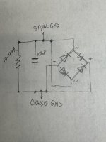
Speaking of rectifiers, here's what I did for my DAC. Three 10V supplies for PMD100 and DIR9001 and one +/-18V for 8*PCM1702.
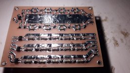
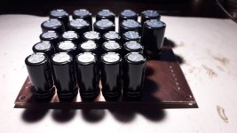
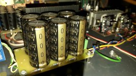
Low VF Schottky bridge rectifiers and CRCRC... filters, 15pcs 2200uF/25V + 10pcs 3900uF/25V, all Nichicon UHW, resistors Vishay MELF 1W, and small capacitors COG + SMD film were used.
Otherwise, this kind of rectifier makes sense with shunt regulators when the currents are constant and when the CRC filter does its job properly. After filtering, ripple no longer exists 😉 .
The analog section has the same type of rectifier but with 6 Nichicon LKG 4700uF/35V on a separate PCB.
Attachments

The bridge only setup is what’s used in pearl psu. It only conducts when voltage is above diode Vf setting Works for safety. It’s by no means the only way to do this.Hi Randy,
I was looking at the ground loop breaker and it’s missing the parallel resistor and capacitor between signal gnd and chassis gnd.
Or omit the BR and use a thermistor//capacitor between sig gnd and chassis gnd.😉
I use a CL60 thermistor in power amp PSUs for this function.
I’m happy to update this PCB to TH and cap instead of bridge. Is there a consensus on which TH? CL60 is big. ZM uses a smaller one on IronPre. I could go for that one. Although I like CL60 because I buy them in bulk.
- Home
- Source & Line
- Digital Line Level
- DAC AD1862: Almost THT, I2S input, NOS, R-2R