https://www.ebay.com/itm/155463932948Another PCM63 DAC lives! DIR9001 into miro1360 pcm and Lundahl output stage, with Sparkos PSU
Ran into one issue with setup and I'm looking for feedback. Is 24bit I2S a requirement? My initial test
resulted in no low bass with a 16bit SPDIF signal. Setting output to 24bit via SMSL PO100 from my PC
finally resulted in a full audio bandwidth. I see most people are using I2SoverUSB or something similar.
Do I need a different SPDIF to I2S board that supports 16bit I2S? I'd like to use my high quality 16/44
CD transport if possible. Thanks!
https://www.ebay.com/itm/354837894318
There were no problems with AK4113 board. AK4118 is a new board, we haven't tried it yet. Power supply required +5V 50mA.
The card has an I2S input, so a USB/I2S card can be added if desired.
Thanks NIXIE62! I ordered parts & PCBs to build the WM8804 that was posted, so I'll try that. That looks like another nice option and less than what the parts and PCB costs for the WM8804. Screen is a bonus also!
Something is wrong with the DIR9001 settings or the DAC itself. DIR9001 does not care if it receives 16 bits or 24 bits or something in between, it must not affect the bandwidth.Another PCM63 DAC lives! DIR9001 into miro1360 pcm and Lundahl output stage, with Sparkos PSU
Ran into one issue with setup and I'm looking for feedback. Is 24bit I2S a requirement? My initial test
resulted in no low bass with a 16bit SPDIF signal. Setting output to 24bit via SMSL PO100 from my PC
finally resulted in a full audio bandwidth. I see most people are using I2SoverUSB or something similar.
Do I need a different SPDIF to I2S board that supports 16bit I2S? I'd like to use my high quality 16/44
CD transport if possible. Thanks!
For example, in my DAC, I have dir9001 configured to play everything, including 24/96 (the digital filter receives 24/48 max), but the output of the digital filter is configured to always output 20 bits for PCM1702 (new version of PCM63).The logic (6x74HCT164) in miro DAC should also be set to output 20bits according to PCM63.
However, since I mostly listen to CDs the signal is always 16-bit 44 or 48kHz, I don't bother with 24-bit and anyway there is very little music in that format that is well recorded in 24-bit or remastered from 16-bit.
Yeah, I'll know better when I have another receiver to play with. It's a cheap prebuilt DIR9001 PCB, so who knows if there is a mistake in the adaptation of the circuit. Just the 74HCT164's between the receiver and the DACs, I would think that 24bit would be a problem also if there was an issue there. All parts on the DAC are from Mouser and carefully soldered. I do have extra PCBs and parts for another DAC board if need be also. Housing should be here soon and I can make it look a little nicer also.
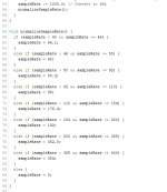
Few days ago some one shared a module from aliexpress, the module could be attached with the DAC and it displays the sample rate by reading only one signal i.e; LRCLK, so I decided to give it a try, when I thought about it, the solution seemed very simple so I have written up the code.
The code is for arduino and an I2C 20x4 LCD is attached as display, frankly, I haven't tested it yet but I am pretty sure it will work either directly or with some tweaking. So here is the code, please feel free to use it.
@miro1360 I think we can also utilize the CPLD, as it has enough horse power, free pins and flexibility.
So in my planned setup CPLD will be performing the logic conversion, signal switching between 3 I2S signals (USB, Optical, Bluetooth) and displaying the sample rate on the LCD/OLED along the input signal. Any other display could be adopted like ILI9341 etc or 128x64 I2C OLED.
Attachments
Last edited:

@rehanabid Great arduino code, it should work 😊
I am not sure about CPLD, if it has enough resources for all this (FPGA sure has), you need to try 😉
I am not sure about CPLD, if it has enough resources for all this (FPGA sure has), you need to try 😉
Thanks miro1360, gave the code a try myself, used ssd1306 I2C and here is the result.

I realized some errors in the code in the sense that LRCLK carries stereo signal instead of single channel, therefore it had to be adjusted.
HD44780 20x4 LCD will be the same, slight changes from the last code instead of Hz the code is now calculated in KHz and displayed as such, since I am out of time this weekend so I leave further tweaking to the DIY community. I guess as POC it works.
Here is the modified code for SSD1306 I2C oled.
Attachments
Attachments
Thanks @miro1360 I was experimenting with the code before I embarked on yet another 10 days travels, was trying to normalize the code as you suggested, with something like this one, but will be able to give it a try next weekend.@rehanabid It looks very good 👍
You can add a code for normalizing the sample rate:

last upload to arduino did not resolve the underlying issue, will try your approach of adding another function "normalize Bit Rate", I am sure it will work. Thanks for the continued help to the DIY community and lazy people like me. Once I am done with this part, I think the next logical solution is to develop this one to have IR capability of signal switching by replacing the toggle switch and a display of input between (USB, Coaxial/optical, and bluetooth)
Last edited:
Dear all,
I am giving away two bare PCBs of miro1360 TDA1541 DAC free of cost to anyone on the basis of first come first served with following conditions:

I am giving away two bare PCBs of miro1360 TDA1541 DAC free of cost to anyone on the basis of first come first served with following conditions:
- Interested person drop me a PM.
- Only 1 PCB per person.
- Interested person to pay shipping charges depending upon the country they vary from $10 flat to $15 flat via regular post
- Tracking ID will be provided once the board is shipped, the tracking ID is valid till the board reaches your local post office.
- I am usually traveling locally/Internationally so shipping can be delayed by a few days till the time I get back home.
@rehanabid, in your post #7390, did you notice in the "if..." line, you have the "44100" and "47000" values reversed with each other. As it stands, the condition of that line will never be true.
Hi Bensen,Hello,
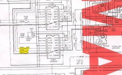
Is it beneficial to add resistors right before the digital inputs of the AD1862? I notice Denon does this in the DCD2560.
330R and 1K are the values.
Regard
In my perspective those resistors are added to reduce ringing following signal transitions (rising and falling edges), due to parasitic capacitive and inductive effects (which cause transmission line impedance mismatch), the higher the R value the lower the overshoot (or undershoot). There is, however, a drawback, since the digital inputs typically also present some capacitance, the slope in the transistions can be decreased if the value is set too high (typically over 1 k). The best way is to check this effect with an oscilloscope.
In some cases the resistors can be omitted and the system works fine, in others the ringing is too high for adequate operation (i.e. the system will assume ringing as signal transitions).
In AD1862 capacitors C7,C8,C17,C18,C27,C28,C32,C33 according to BOM should be Nichicon 100uF MouserNo:647-UKW1E101MED. This capacitor is End of Life. Is better to replace them with Panasonic 667-16SEPC100MW?
Also Nichicon 4,7uF C15,C25 is not available. What to use instead ?
Also Nichicon 4,7uF C15,C25 is not available. What to use instead ?
EOL doesn't mean they are sold out. It's just that it wont be manufactured any more. Nichicon killed off a lot of audio grade caps. These you can still purchase.
I used Panasonic EEU-FC1H4R7 for the 4.7uf
My favourite these days for 100uf 25v caps :
https://www.digikey.sg/en/products/...yVEDACsdAGptOPSP2FjJ0uYpWqTxwrgHY68sgBGdGzKQA
i am using them for most of my dac now.
My favourite these days for 100uf 25v caps :
https://www.digikey.sg/en/products/...yVEDACsdAGptOPSP2FjJ0uYpWqTxwrgHY68sgBGdGzKQA
i am using them for most of my dac now.
But Brijac is correct. EOL simply means stock them up while you can.
However i am sure they would come up with new series of audio caps to replace the EOL ones... won't they?
However i am sure they would come up with new series of audio caps to replace the EOL ones... won't they?
- Home
- Source & Line
- Digital Line Level
- DAC AD1862: Almost THT, I2S input, NOS, R-2R