 Gentleman, let's be, shall we?
That looks fantastic. I was already intersted in this WJ set-up with this op amp. I see you build some kind of super reg on it. My idee too. You mention you would share the gerbers. Could you maybe also insert the values of the components of the i/v for the ad1862? And of course i am courious for your oponions about this set up.Well, I tried my best to stay content with my current MiroDac setup and resist tweaking……
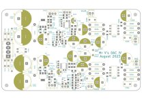
But, the recent chats about using the AD811 opamp as IV kept picking away at me. So, with lots of help from my friend for the pcb layout this IV board is ready for some listening. The circuit is inspired by Grunf’s adaptation of Walt Jung’s shunt regulator/AD811 IV work he shared here and on other threads. (Thank you Grunf!)
After some listened time and more tweaking I’ll share the gerbers via PM to those that are interested😉
Sure will Arnolddew😉
In order to keep the this project as compact as possible I added a bridge rectifier, snubbers (use Quasimodo jig for values) and CRC filter before the Grunf/WJ shunt regulator section. This will eliminate a separate psu board and wiring. The revised pcb’s should arrive this week, then I’ll build a board to verify all works without bugs. I did have a few labeling errors on the current version that caused a few hairs to be pulled out if my head, Hehe!!
With the amount of listening I’ve done so far, this IV stage with integrated power supply sounds great.
Attachments
Vunce,
I agree with Miro, a great design.
By the way what voltage are you running the I/V at?
I agree with Miro, a great design.
By the way what voltage are you running the I/V at?
Thanks Fellas, but I’m just a “mimicker” of already vetted designs.😊
@BRN,
Input = 15-0-15vac
AD811 supply voltage = 11.60V
I don’t have heatsinks for the AD811 opamps yet, so wanted to keep them from getting to hot.
There are programming resistors in the shunt supply to adjust output voltage. I believe Grunf runs 14V to the AD811, but heatsinking is mandatory for that.
Nice, thank you very much, Vunce.
EDIT:
I don't know if you already mentioned, but what type of transformer are you using and what is it's nominal voltage/current rating?
EDIT:
I don't know if you already mentioned, but what type of transformer are you using and what is it's nominal voltage/current rating?
Last edited:
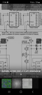
If you are using the version which has JLsounds on top, the JLsounds need to be configured as 'pcm1704 like configuration' to output the R and L data, hence the shifters are not needed.
If you are using the board with the shifters, the JLsounds board will be connected in the usual i2s signal configuration to the dac board inputs.
If you are using the board with the shifters, the JLsounds board will be connected in the usual i2s signal configuration to the dac board inputs.
Since we are on this, i would like to share that the lastest JLSounds I2SoverUSB FIO board has a different way of configuration as compared to the previous version.
If you are using the DAC board with the JLSounds I2SoverUSB FIO board on top, you do not need to install R13 (4.7K) on the Miro board anymore.
On the JLSounds board, use this configuration as stated on page 6 of the user guide :

If you are using the DAC board with the JLSounds I2SoverUSB FIO board on top, you do not need to install R13 (4.7K) on the Miro board anymore.
On the JLSounds board, use this configuration as stated on page 6 of the user guide :
Last edited:
- Home
- Source & Line
- Digital Line Level
- DAC AD1862: Almost THT, I2S input, NOS, R-2R