I didnt use any logic before dac. Just receiver IC (with one inverter).From the specs, max Vcc of 74HCT164D is 7v, did you use a separate power? Or you did not use shift registers?
Dacs and other logic have been used with separate supply.
.
But off-course that You can use Vdigital of 12V, step down to +5V or +3.3V for digital ICs before DACs.
Also You can use +-12V Vanalog from DAC to suply analog output circuit.
Just not to connect digital GND and analog GND. BUT CHECK eventual diference in voltage between GND D and A
and compare with datasheet max dif value.
.
Bare in mind that all voltages in any dac is in the same time and Anlog and Digital.
Inspired of that they are "marked" as separate D and A... 🙁 that is not true.
It is more true that they are DA in the same time...
.
The right way to treat tha AD system is to have all diferent syplys and DAC circuit has to be galvanicaly isolated from bootha sides.
Then You will have:
Digital (digital circuit with own supply)
isolation (digital)
Digita/Analog (dac circuit with own supply)
islation (transformer)
Analog system only (analog circuit with own supply)
The limit from the datasheet is a bit more than 13V. So You can go even to 13V or to the limit. Check the I consumption too. I remembered that the chip was not significantly warmer and that can be used without the heat sink.-VD should not be less negative than -VA, that's why I planned -10V and -12V, to be on the safe side. That's the limit from the datasheet.
.
If it is stated about the datasheet about the diference in - V suplys stick to that. BUT i am not sure about that.
.
More important is that GNDs are not diferent more than value spec in the datas.
.
If the value is higher put 2 diodes in opposite between the ground points.
Yes, 13V is a limit, but I always practice a little less than the max. per datasheet. The exception is DDDAC, there are limits for PCM1794A - Vdd=+4V, Vcc=+6.5V and Doede supplies it with +8V for both parts. And it works. The PCM1794 is a little beast, with an output current of 10mA (at +8V supply). Connect multiple pieces in parallel, and you don't need any output stage, just one I/V resistor. 😎
Last edited:
Good to know, so others won't just increase the voltage on Miro's board and possibly damage the shift registers.I didnt use any logic before dac. Just receiver IC (with one inverter).
Dacs and other logic have been used with separate supply.
I followed Miro's good sounding original design using 5V.
Yes offcourse - but every single component has own max value of PS?
Should be checked before connectiong any PS? 🙂
There is no original design - everything is happening in the borders of manufacturers measured datasheets values...
Should be checked before connectiong any PS? 🙂
There is no original design - everything is happening in the borders of manufacturers measured datasheets values...
Got 'chips in the mail' and wonder if anyone has gerber files for the AD1862 board without the I/V stage? I know there is a version without the shift registers and I/V stage (for JL sound), but was interested in building a version with the shift registers and no I/V stage.
Cheers -
Cheers -

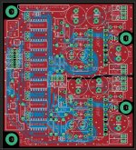
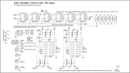
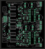
Here it is, the same as in post #1, but:
- only current output (no I/V on the PCB)
- analog part has independent power supplies (VAL, VAR)
- 8th pin on I2S input header is connected to the GND (on some of my PCBs this pin is unconnected)
Attachments
For the AD1862 board, what are people preferring for the +/-5v digital power supply? I see that Miro has designed a few options in this thread. I have Salas shunts for the +/-12v analog supply and could do another set of these for the digital.
Cheers, Soren
Cheers, Soren

Just remember that -VD should not be less negative than -VA. So take a slightly lower voltage for the digital part, say +-11.5V or less.For the AD1862 board, what are people preferring for the +/-5v digital power supply? I see that Miro has designed a few options in this thread. I have Salas shunts for the +/-12v analog supply and could do another set of these for the digital.
Cheers, Soren
I'm having a weird problem with JLS I2S over USB cards in all Miro DACs I've been building. Of course it has nothing to do with the DAC, only with the USB card.
I am using WIN 10 LTSB and a separate PC for audio only. Everything works normally, except that when I use Album Player free, the volume control in the player does not work, regardless of which driver I use (ASIO, KS, WASAPI). I select the option to have variable volume in the player, but it doesn't work, it's always at max. volume. That player gives me the best sound of all the ones I've tried.
I also tried Foobar and AIMP players and the volume control works fine there, but the sound is not as good as with AP free. I also have an older DAC with a WaweIO USB/I2S card (DDDAC with PCM1794A) and with it the volume control works in all players.
Any idea why that is, and if I can somehow get it to work?
Here is the link for that player:
https://vvfon.ru/aplayer_eng.html
@NIXIE62 Perhaps a good time to test my headphones amplifier with potentiometer volume control and leave digital pot on 100%? 😁
Resistors combination R1/R2 works as fixed attenuator (with default values it will reduce the voltage by half), the formula is Vout = Vin * (R2 / (R1+R2)).
Next stage is the combination R3 with R4 and this is gain. Gain formula is: G = 1 + R4/R3 ... with default values G = 1 + 820/820 = 2.
Example: DAC output voltage = 1.7V ... after attenuation = 1.7 * (5k6 / (5k6 + 5k6)) = 0.85V ... after gain = 0.85V * 2 = 1.7V
.... so for a higher output voltage you can either remove the attenuation (not installing R4) and working only with gain, or just increasing the gain (by increasing R4).
Build notes:
This version with DC servo is not tested yet. It is tested without DC servo and works great 😉
- TPA6120 based
- It can function as a preamp with volume control (and it does, I tested it)
- DC servo (can be omitted)
- Relay as output selector (either direct output or headphones output) ... relay can be omitted (then manually bypass the relevant relay pins)
Resistors combination R1/R2 works as fixed attenuator (with default values it will reduce the voltage by half), the formula is Vout = Vin * (R2 / (R1+R2)).
Next stage is the combination R3 with R4 and this is gain. Gain formula is: G = 1 + R4/R3 ... with default values G = 1 + 820/820 = 2.
Example: DAC output voltage = 1.7V ... after attenuation = 1.7 * (5k6 / (5k6 + 5k6)) = 0.85V ... after gain = 0.85V * 2 = 1.7V
.... so for a higher output voltage you can either remove the attenuation (not installing R4) and working only with gain, or just increasing the gain (by increasing R4).
Build notes:
- All capacitors and connectors can be installed from the bottom, then mounting spacers can be used to mount the PCB on the front plate.
- The big hole under TPA6120 IC is for soldering. When you solder all the TPA6120 pins, finally solder the TPA6120 from the bottom to the PCB through this hole.
This version with DC servo is not tested yet. It is tested without DC servo and works great 😉
Attachments
-
diyAudio_Headphone-Amplifier-2_only_2023-05-30.zip421.9 KB · Views: 125
-
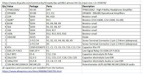 diyAudio_TPA6120-IV_Headphone-Amplifier-2_only_BOM.jpg150.1 KB · Views: 385
 -
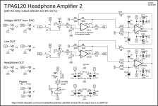 diyAudio_TPA6120-IV_Headphone-Amplifier-2_only_Schematic.jpg290.8 KB · Views: 321
 -
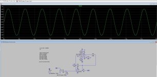 diyAudio_TPA6120-IV_Headphone-Amplifier-2_only_Simulation.jpg228.2 KB · Views: 378
 -
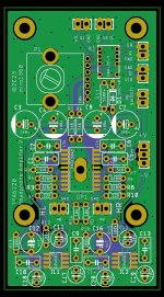 diyAudio_TPA6120-IV_Headphone-Amplifier-2_only_TOP.jpg226.8 KB · Views: 325
Last edited:
- Home
- Source & Line
- Digital Line Level
- DAC AD1862: Almost THT, I2S input, NOS, R-2R