
Volume never worked with JLS + Album Player. Maybe with old WIN driver version.I am using WIN 10 LTSB and a separate PC for audio only. Everything works normally, except that when I use Album Player free, the volume control in the player does not work, regardless of which driver I use (ASIO, KS, WASAPI). I select the option to have variable volume in the player, but it doesn't work, it's always at max. volume. That player gives me the best sound of all the ones I've tried.
I'm not much of a fan of headphones, I prefer loudspeakers. I find headphones very harmful, and I don't like music in my head. 🤣@NIXIE62 Perhaps a good time to test my headphones amplifier with potentiometer volume control and leave digital pot on 100%? 😁
I have a few pieces, nothing particularly high quality, I rarely use them. I leave it to the younger ones to try it out. 😎
Last edited:
I also asked Lyuben from JLS, maybe he knows why. Other cards with XMOS chip work without problems with volume adjustment in AP. And other players do it with JLS. Maybe I should ask the author of AP why that is?Volume never worked with JLS + Album Player. Maybe with old WIN driver version.
Ok, I understand that. But I have several preamps, two with tubes (one is buffer Gain=0.95) and one SS. I think the preamp has to be with tubes, if everything else is SS, to bring some life to the music.
SS preamp is with OPA and then Mosfet source follower, to get Class A and Single ended mode. Tube premp is Broskie Aikido with Tesla 6CC42, buffer Aikido cathode follower with Amperex E88CC.
SS preamp is with OPA and then Mosfet source follower, to get Class A and Single ended mode. Tube premp is Broskie Aikido with Tesla 6CC42, buffer Aikido cathode follower with Amperex E88CC.
Why do you use digital volume control? Use preamp. I read that digital volume control degrades sound, not sure if that is true 🤔
Yes, it does indeed, because it reduces dynamic range, if I'm correct most (if not all) SW volume controls work by floating point conversion of samples and division (or less than 1 factor multiplication), followed by another floating point integer conversion. When you reduce volume by 6 dB, for example, you drop from -32768 to 32767 range to -16384 to 16383 (assuming a 16 bit file), to get half the voltage (or current) at the DAC's output, if I understood right how it works. Now imagine 10 dB or more of attenuation, I rest my case 😏
Last edited:
I'm not that young to get up all the time. 😏Why do you use digital volume control? Use preamp. I read that digital volume control degrades sound, not sure if that is true 🤔
And almost every file has a different volume.
I don't know if it's because of that, it depends a lot on the player, how the digital volume is done. And the classic analog potentiometer has a bad effect on the sound, probably more than that digital control. That's why I switched exclusively to rotary switches with SMD resistors. I didn't notice much degradation with digital volume, when not correcting too much. When I listen dedicatedly, the digital volume is at 100%. When I listen casually, I use digital volume.Yes, it does indeed, because it reduces dynamic range, if I'm correct
Here the Gerber files and the BoM :
1x IC1 AD797 SOIC8
facing downwards
1x Riv Susumu 0805 27R 0.5%
1x Rs Susumu 0805 27R 0.5%
1x Rf Susumu 0805 2.7k 0.5%
2x Cs Murata C0G 0805 10nF 25V
1x Civ Murata C0G 0603 2.2nF 50V (solder between Pins 2 & 3)
1x C8 Murata C0G 0603 51p 50V (for AD797 only)
Many thanks to Fran for verifying PCB.
Enjoy,
Patrick
Civ Murata C0G 0603 2.2nF 50V (solder between Pins 2 & 3)
<=
I don't know which pins 2 & 3 are?
Is there anyone who might show me a picture of soldered PCB?
Pin 1 is already indicated on the board on 2nd pic. So solder civ across pin 2 &3 on the smd op amp.Civ Murata C0G 0603 2.2nF 50V (solder between Pins 2 & 3)
<=
I don't know which pins 2 & 3 are?
Is there anyone who might show me a picture of soldered PCB?
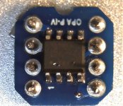
View attachment 1196972View attachment 1196973
We'll, this Gerber was posted here, so right thread.
https://www.diyaudio.com/community/...st-tht-i2s-input-nos-r-2r.354078/post-7319860
The half circle cutout is the same as in a DIP8 package, indicating pin orientation.
Pin 2, 3 are where Riv is connected.
And Civ is in parallel with Riv, without saying.
You cannot solder Civ at the SOIC opamp.
You need to solder directly next to Riv at the round pads for the DIP8 pins.
Patrick
Last edited:
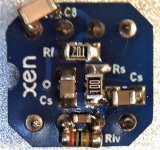
I hope the following picture help.
The "1" on the underside of the board is for alignment to pin 1 of the AD797. Then the cut-out notch shows the orientation for plugging it into the op-amp socket in the DAC board. You can see how I used a melf resistor for Riv and a ceramic cap for Civ in between the pins for 2&3. The only cap I had to hand for C8 was a little large, so it hangs off the side a bit!
I mounted mine in an op-amp socket and then can easily plug that into the DAC board.
Don't forget - you must remove Riv and Civ if they are installed on the DAC board!!!
My original post is here
fran
Attachments
This is good! Will you put this into your blog as well?Here it is, the same as in post #1, but:
Otherwise no significant changes 😉
- only current output (no I/V on the PCB)
- analog part has independent power supplies (VAL, VAR)
- 8th pin on I2S input header is connected to the GND (on some of my PCBs this pin is unconnected)
- Home
- Source & Line
- Digital Line Level
- DAC AD1862: Almost THT, I2S input, NOS, R-2R