Beather the OP is tube outpit.Nah. there is no way it will play like this with Muses02 whatever you construct.
I'm going to weld the cover on this DAC.🤣
For active I/V it's not a problem, only for passive. The PCM1794A apparently does not have that problem.
Fumihiko actually said paralleling is great. But each chip has to be decoupled individually. And it has increased the quality dramatically.Don't do the mistake, look at this thread:https://www.diyaudio.com/community/threads/pcm63pk-in-piggy-back-mode.51032/
PCM63 is too expensive for that. I thought of these other cheap ones, try some and see what happens.
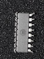
it is suspicious to me because of the belly, where the numbers have disappeared? if they are not there it means that it has been sandblastedPHL = Phillippines and it is not K. By the way, I've seen other chips with that design, say PCM56, and that worked.
Attachments
Parallel connection of current DACs improves their characteristics, that's why I have eight PCM1702. Then the output voltage is calculated according to the formula Vp-p = +/-Idac x N x Rf. Each IC must have its own decoupling and a very well designed PCB for all.
And as far as op-amps are concerned, most of you make big mistakes, for all new op-amps decoupling is required right next to the op-amps themselves i.e. the supply pins themselves, at least ceramic 0.1uF. Even an ordinary soic-to-dip adapter makes a difference due to the length of the lines and can spoil the characteristics, especially if we are talking about devices where higher frequencies are present, such as a DAC.
The OPA1611 cannot work well without decoupling along the pins themselves, which is nicely written in the DS itself, you just need to read it. From my practice, 10nF COG is enough to calm it down, while, for example, the ADA4625-1 needs much more.
Maybe...Maybe not. It depends on the taste.😗Beather the OP is tube outpit.

Check.@ra7 DAC chip should not be damaged.
Start with controlling all voltages directly on the DAC pins, be very careful not to short anything, (pin 28=5V, 26=-5V, 15=-15V)
Check.Check voltages on the I/V opamp pins.
Check.Measure +5VD voltage on all digital IC capacitors.
I have a scope and can put it to use. Meanwhile, yes, ac on pins out from streamer and ac on dac pins 1, 2, 3, 4.Do you have a digital analyzer to view data stream on digital pins? If not, turn your multimeter and measure AC voltage on digital pins. Play music and measure digital pins on the USB streamer (measure on disconnected from DAC and then on connected with DAC). You should see some AC voltage on your multimeter while playing music. Then measure digital pins on DAC chip if there is some AC voltage (pins 1, 2, 3, 4 with the GND pin 14).
🙂
What to check next?
647-UFG1H4R7MDM for C15,C25 in AD1862 BOM is end of life.
Is there any other recommendation?
There is 647-UFG1H2R2MDM1TA (2.2uF).
Is it proper for C15,C25?
Is there any other recommendation?
There is 647-UFG1H2R2MDM1TA (2.2uF).
Is it proper for C15,C25?
https://www.hificollective.co.uk/wire/mundorf-silvergold-wire-110sgw.html
I put this wire as I2S - holy s*it how much better this is now. - I soldered directly to the resistors😎

I put this wire as I2S - holy s*it how much better this is now. - I soldered directly to the resistors😎
You can use it, but then use 22uF for C16, C26: https://www.mouser.sk/ProductDetail/Nichicon/UFG2A220MPM1TD?qs=j%2B1pi9TdxUar4F%2BVvlr%2BLA==647-UFG1H4R7MDM for C15,C25 in AD1862 BOM is end of life.
Is there any other recommendation?
There is 647-UFG1H2R2MDM1TA (2.2uF).
Is it proper for C15,C25?
Or alternatively you can use this panasonic 4.7uF: https://www.mouser.sk/ProductDetail/Panasonic/EEU-FR1H4R7?qs=tfZGHB2PWd0gZ8LzVWIqKg==
Soo, all these fancy cables really work? 🤔holy s*it how much better this is now.
Of course. It doesn't work without a cable.😉Soo, all these fancy cables really work? 🤔
Here are pics from the scope measurements. Thanks Miro!
Pin 1,2,3,4
Attachments
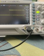
A funny thing happens, which is that after turning off the supply, the 5V line near the logic chips still retains 2V and the LED glows faint. I can see this on the scope at pin 1 of the DAC. That means the supply cap is not draining, which might mean something is open when it shouldn’t be.
Edit: the 2V is coming from the USB Streamer. It goes away when I disconnect the USB cord.
Edit: the 2V is coming from the USB Streamer. It goes away when I disconnect the USB cord.
Last edited:

@ra7 Can you check the USB Streamer settings and set the sampling frequency to 44100 kHz and test the sound again? 🙂
If no sound, put the scope on pin 3 or 4 and see the scope if there is some data present and alternating while the music plays (you can compare it with the situation when music is paused).
If no sound, put the scope on pin 3 or 4 and see the scope if there is some data present and alternating while the music plays (you can compare it with the situation when music is paused).
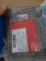
Mine just arrived at my door but I have no pcm63p chips....🤣🤣Thanks to @floyd89gr I have a new PCB and a new occupation.
Attachments
- Home
- Source & Line
- Digital Line Level
- DAC AD1862: Almost THT, I2S input, NOS, R-2R