Here is my caps plan

R8 and R9 - that's where Dale MIL CMF goes (Very low noise (-40 dB)) 0.1% - 50ppm 😀
R8 and R9 - that's where Dale MIL CMF goes (Very low noise (-40 dB)) 0.1% - 50ppm 😀

Due to the special operation of economy (sanctions) , caps therapists became too much expensive...uh.
Last edited:
It´s playing on both annels ,I must have my accident burnt one chip.Now on to mounting the D1 pcb.

Last edited:
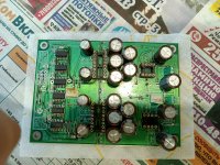
Some progress to report. I finally got all of the required parts in and was able to stuff the board. I took Vunce's esteemed advice and conserved real estate on the top of the board near the opamps and DAC chips by relocating stuff on the bottom of the board. I used the revised BOM that was posted in this thread for my guide in doing this build, but I do have a question. It states that the RC filter which uses C37 and C38 can be omitted. On the rev 1.3 board that I'm using I can't find any C37 or C38. I'm guessing that C27 and C33 may be the new labeling for these caps on this board because of the proximity to R10 and R11. Is this the case? if it is I have two choices, remove C27/33 or add R10/11. I'm guessing that less is better, so is removing C27/33 might be the better move.
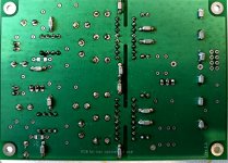
Anyway, here are some pics , if you see any errors please shout out to me, I've gotten really good at screwing things up.
next I'm going to turn my efforts to installing the three PSUs (2for DAC, 1 for waveIO) that I'll be using on my project board and make sure that they're all working correctly next. Once that's all done I hook everything up without the dac chips or opamps installed and do a power up test to see if there are any problems. I'm looking forward to hearing this DAC play.
Attachments

The two 47 pF surface mounts are not always necessary related to the opa you choose, and it may be risky to use ceramic class 2 here (cause it could be piezzo). At the end you will check by a listening session.
But the waiting output resistors, it seems good. 👍
But the waiting output resistors, it seems good. 👍
https://bispa.co.jp/blog/1774
There are new resistor from alpha electronics.
I have not compared yet.
There are new resistor from alpha electronics.
I have not compared yet.
@sworder84, I've been playing with the PCM1702 for years, it's a great dac i.c. but it will play well only if it has a top power supply and IV stage, otherwise it will sound like cheap Denon CD players from that era when NAD with PCM1710 sounds a lot better.
The shunt regulator is the best choice, for years I used a Salas shunt with a bunch of OS-CONs, for the last couple of years I have a Walt Jung shunt, which is still better but also more complicated and does not have ready-made PCBs.
For decoupling, OS-CON plus smd COG, as close as possible to the pins. Tantalum can be used instead of OS-CON.For reference pins UKZ or another good AUDIO cap. with low leakage current. If you have BG(Black Gate) instead of UKZ it is even better. Unfortunately, my stock of BG cap no longer exists🙁
3,615MHz is present on the power supply pins so you should pay attention to that.
MC7805/7905 will do job for a start, but try to change it to something better.
What also can be made is phantom gnd as per pcb1 but with two positive reg (not with the actual pcb). Because positive regs here are better than their negative rail brother 79xx.
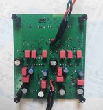
Today almost finished the Dac board. PSU still in progress. Instead Wima and Cemet - NP0 Murata 0.1/50 1206. Opamps will be OPA134PA.
I also install jumpers instead resistors. I waiting only two resistors 1k4.
@grunf what kind PSU I need look for top sound? I have also LM6171 and later a will be looking more expensive.
I don't have Black gate - it's rare items.
I also install jumpers instead resistors. I waiting only two resistors 1k4.
@grunf what kind PSU I need look for top sound? I have also LM6171 and later a will be looking more expensive.
I don't have Black gate - it's rare items.
Attachments
rev 1.3 has no RC filter on the output (that is why the C37/C38 are missing).Some progress to report. I finally got all of the required parts in and was able to stuff the board. I took Vunce's esteemed advice and conserved real estate on the top of the board near the opamps and DAC chips by relocating stuff on the bottom of the board. I used the revised BOM that was posted in this thread for my guide in doing this build, but I do have a question. It states that the RC filter which uses C37 and C38 can be omitted. On the rev 1.3 board that I'm using I can't find any C37 or C38. I'm guessing that C27 and C33 may be the new labeling for these caps on this board because of the proximity to R10 and R11. Is this the case? if it is I have two choices, remove C27/33 or add R10/11. I'm guessing that less is better, so is removing C27/33 might be the better move.
Anyway, here are some pics , if you see any errors please shout out to me, I've gotten really good at screwing things up.
next I'm going to turn my efforts to installing the three PSUs (2for DAC, 1 for waveIO) that I'll be using on my project board and make sure that they're all working correctly next. Once that's all done I hook everything up without the dac chips or opamps installed and do a power up test to see if there are any problems. I'm looking forward to hearing this DAC play.
C27 and C33 (100u - 330u) are for opamps power supply, you need these on the PCB !!!
C31 and C36 (47p) are for the I/V, better to let it empty because some CFA opamps hate this capacitor.
... so for you: Remove the C31/36 from the PCB ... but the C27/C33 must stay on the PCB 😉
Correct, you need one PSU-1 PCB for the PCM1702, where you install 2x MC7805/7905 regulators (resulting in 2x +-5V) .... R8/R7 is 330R and R9/R10 is also 330R 🙂@miro1360, I have a question about PSU-1. I need two 5V instead 12V for 1702 right? I have a two pair MC7805/7905. I should solder R8/R7 - 330R. What's about R9/R10 pair - 1K or also 330R?
I have no heatsink for stabs 5V. Is it ok?
1k4 value is not critical, you can install also 1k5 (the output volume will be "higher") or 1k2 (the output volume will be "lower") ... this resistor sets only the output volume from DAC ... this resistor is optional based on your output voltage (volume) request 😊Today almost finished the Dac board. PSU still in progress. Instead Wima and Cemet - NP0 Murata 0.1/50 1206. Opamps will be OPA134PA.
I also install jumpers instead resistors. I waiting only two resistors 1k4.
For the participants in this thread, what I2S data streams are you feeding this board? Unfiltered, native-rate PCM or...?
Apologies if this is beyond the scope of the thread, looks like you guys are working with some nice hardware...
Apologies if this is beyond the scope of the thread, looks like you guys are working with some nice hardware...
I'm aware of the possibilities... I was wondering what folks are doing in practice.
I.E. I feed my 20 bit converters from a similar input circuit, amongst others, with 24bit, 8x or 16x un-dithered PCM data.
I.E. I feed my 20 bit converters from a similar input circuit, amongst others, with 24bit, 8x or 16x un-dithered PCM data.
- Home
- Source & Line
- Digital Line Level
- DAC AD1862: Almost THT, I2S input, NOS, R-2R