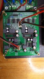
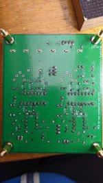
I would put some more flux on all pins and just go across all pins with soldering iron... Some pins on ic1 and ic2 you can still see pads...
exactly what I was going to write to Ernst at seing the picture... and a little more heat maybe.
you still can buying ad1862 on chineese sites, but it is now ridiculous expensive, as expensive if not more than Rochester which are unused parts with premium guranty, since this project increase the purchases.
Wow, they have gotten expensive! Same price as ever here in the swap meet for Rochester-sourced chips... 🙂
Good afternoon, thanks for your proposals. I'll do, even I have checked all the solders. They are all OK. Maybe not enough?
The strange thing for me is, that I have the same signal on both channels. Is there a theory for that?
Will report back.
Cheer's
The strange thing for me is, that I have the same signal on both channels. Is there a theory for that?
Will report back.
Cheer's
I just started dac board with diy jumpers. 😀😀 Still wait on mousers parts to arrive. Can’t wait 🤓
Good afternoon, thanks for your proposals. I'll do, even I have checked all the solders. They are all OK. Maybe not enough?
The strange thing for me is, that I have the same signal on both channels. Is there a theory for that?
Will report back.
Cheer's
Can you a couple of pictures of your full board?
Good idea to use c0g caps on underside near shift registers.
Maybe there is a fault on underside, wrong connection to GND from latch enable signal i would check that fitst
Maybe there is a fault on underside, wrong connection to GND from latch enable signal i would check that fitst
the dac choice in the playback renderer perhaps 😕 ?
If your smd caps are not ceramic class II, better to go for ceramic class I, or sorted out PPMS if you have some in your tool box from another project anf id its width fits the vias gap.
If your smd caps are not ceramic class II, better to go for ceramic class I, or sorted out PPMS if you have some in your tool box from another project anf id its width fits the vias gap.
I think that is a different board version to mine - it doesn't have the label text for i2s and doesn't have the revision number. Could there be an error on the board or a setup difference maybe?
Which was tested and is proven, so its not that.
Time to double check the source I suppose?
Continuity checks from the shift register point where data L and R come from?
Time to double check the source I suppose?
Continuity checks from the shift register point where data L and R come from?
Thanks guys for your answers!
Fran, strange thing is, that they come from the appropriate location,
and as I see this, the board does not let me make any mistake here. There is a direct connection from pin 7 (data) to the appropriate shift register. Continuity check was done.
Iggy, I had tried some different ones, yet the generic i2s should be ok. I also checked, if volumio, which I used, was switched to the left channel only, even this never happened before. Yet I did not find a swith for that within.
I used Miros "original" BOM (in this case from EASY DAC) for that. TME delivers just 100 of them, so there were plenty. Maybe I find some others in my drawer.....
Tubee, I had done all the check for shorts and I did it again. No short between grd and lrck.
So hopfully I get set up a very old USB2i2s board (from first DDDAC) and will be able to test it again.
Will report back.
Have a good day 🙂
Fran, strange thing is, that they come from the appropriate location,
and as I see this, the board does not let me make any mistake here. There is a direct connection from pin 7 (data) to the appropriate shift register. Continuity check was done.
the dac choice in the playback renderer perhaps 😕 ?
If your smd caps are not ceramic class II, better to go for ceramic class I, or sorted out PPMS if you have some in your tool box from another project anf id its width fits the vias gap.
Iggy, I had tried some different ones, yet the generic i2s should be ok. I also checked, if volumio, which I used, was switched to the left channel only, even this never happened before. Yet I did not find a swith for that within.
I used Miros "original" BOM (in this case from EASY DAC) for that. TME delivers just 100 of them, so there were plenty. Maybe I find some others in my drawer.....
Good idea to use c0g caps on underside near shift registers.
Maybe there is a fault on underside, wrong connection to GND from latch enable signal i would check that fitst
Tubee, I had done all the check for shorts and I did it again. No short between grd and lrck.
So hopfully I get set up a very old USB2i2s board (from first DDDAC) and will be able to test it again.
Will report back.
Have a good day 🙂
I have now some of Vunces opamp adaptor boards for trying 1656.
In the schematic it shows the 2 smd resistors as 47k5 but you have 100k on your boards. Should I go with the 100k also.? And I assume 100nF on the underside.
What pins do you use for these little boards. The pins I've used before are too short...or atleast the holes in the boards won't allow for the shoulder of my pins to enter.
Thanks!
Hi Jim,
As long as the resistors are the same and above 10k, the value is flexible. At the time I assembled that pair I had 100k 0.1% tolerance Susumu’s in my parts stash already. Yes, the cap is 100nF (0603 size).
As long as the resistors are the same and above 10k, the value is flexible. At the time I assembled that pair I had 100k 0.1% tolerance Susumu’s in my parts stash already. Yes, the cap is 100nF (0603 size).
Last edited:
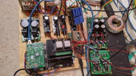
Ja, my IAN DAC is a cable grave. Yet a pretty good sounding one with dcdc less pi, old Andrea clocks, fifopi3, receiverPi, which accepts USB board and spdif. And I like the transformer i/v. So it is a full blown network DAC which deserves a chassis and of course cleaner cable work. One of the next projects. After the easy DAC.
- Home
- Source & Line
- Digital Line Level
- DAC AD1862: Almost THT, I2S input, NOS, R-2R


