A friend designs high end audio gear for a living, has done so for forty years. Wadia, Cary Audio, Pass Labs, and others. He keeps telling me I need a phono setup as an analog reference. He says quickly comparing a good analog audio source with a digital audio source is the only way to know something is still wrong with digital music reproduction. It obviously isn't measured THD+N since digital is much better for that. So, what is it? Friend doesn't know exactly the technical cause, but I believe he is hearing something real. Not sure what he is listening for, but I am guessing it has something to do with the stereo illusion creating a more compelling (real sounding) 3D soundstage.
Last edited:
yeah, I keep my Rega Planar 3 for that . But tha's unfair benchmark, some LPs have great dynamic, some others are so-so. On the other side on CD players and the Red-books I mostly have , it's night and day between the recordings, the AAA sources, the AAD, the ADD, etc ! You really have to know what reccording you're lisstening to ! Here we know, more or less. I'm not sure all the dudes that plays today with LPs understand all of that ! We are a little the last outrage to drosophiles on this forum !
IMD (intermodulation distortion) is one of the main reasons why different topologies sound different ... then digital filters, reconstruction filters, frequency filters, noise, timing, speed, compensations ... when these parameters are mixed, it is difficult to catch any point 😀
... then pcb layout, power supplies topologies, passive and active parts, the resonant link between the devices, and so on !
that's a sport !
that's a sport !
................
My rough understanding is that the data stream is being delayed by a specific number of clock cycles by shift registers, so the corresponding data gets clocked into each DAC channel during the LRCLK cycle.
The problem is that I expected one of channels would be fed directly to DAC and only one would need to be delayed, but it seems shift registers are required for both channels in the schematic...
this is to do with left/right justified data I guess?
This probably won't be possible then without shift registers?
Can I prevail upon the depth of knowledge here. In reading around to understand what is going on in all the bits of this thing, I also have a question on the shift registers. I think I grasp the shifting of the bits so that each word hits the dac chips at the right time. However, reading around on the DDDac site, I see there are references there to half cycle delays, and using a flip flop to sort this out. Can someone explain that to me/us?
Last edited:
I am not sure about DDDAC, it uses PCM1794 and it may differ from AD1862.
AD1862 output updates immediately after LRCK (latch) - the sound depends on the LRCK quality. Thus super accurate synchronization of BCK with DATA is irrelevant.
Many burr-brown DACs, which PCM1794 is, updates the output on BCK cycle. I did not find this detail in the PCM1794 datasheet, but if the output is BCK dependent, then the accuracy of the BCK is important.
On the other hand, BCK is 64x faster than LRCK. If they are generated directly from the MCU, they should be equally accurate (automatically from this source).
@laserscrape
>>The problem is that I expected one of channels would be fed directly to DAC and only one would need to be delayed, but it seems shift registers are required for both channels in the schematic...
this is to do with left/right justified data I guess?
It is due to the same channel alignment. One channel is buffered (is waiting) for the next channel and then they are latched together. Added registers will not reduce the sound quality in any way, because as I mentioned above, the sound depends on the LRCK.
The data is first collected in the DAC (BCK+DATA). AD1862 (20-bit DAC) collects 20-bits and then it generates one specific current level on the Latch cycle (LRCK) from the 20-bit data collection. These current levels form an audio signal over time.
Last edited:
I found after that you posted a diagram which helps illustrate what is happening very clearly.I am not sure about DDDAC, it uses PCM1794 and it may differ from AD1862.
AD1862 output updates immediately after LRCK (latch) - the sound depends on the LRCK quality. Thus super accurate synchronization of BCK with DATA is irrelevant.
Many burr-brown DACs, which PCM1794 is, updates the output on BCK cycle. I did not find this detail in the PCM1794 datasheet, but if the output is BCK dependent, then the accuracy of the BCK is important.
On the other hand, BCK is 64x faster than LRCK. If they are generated directly from the MCU, they should be equally accurate (automatically from this source).
@laserscrape
>>The problem is that I expected one of channels would be fed directly to DAC and only one would need to be delayed, but it seems shift registers are required for both channels in the schematic...
this is to do with left/right justified data I guess?
It is due to the same channel alignment. One channel is buffered (is waiting) for the next channel and then they are latched together. Added registers will not reduce the sound quality in any way, because as I mentioned above, the sound depends on the LRCK.
The data is first collected in the DAC (BCK+DATA). AD1862 (20-bit DAC) collects 20-bits and then it generates one specific current level on the Latch cycle (LRCK) from the 20-bit data collection. These current levels form an audio signal over time.
You also already mentioned that you specifically chose this circuit over stopped clock scheme, since it preserves the original LRCK... wish I had been paying attention because the DIYinHK board's sound quality had always left something to be desired, but I was blaming this on the AD1862s rather than the data interface.
Are the 3.3V logic levels of the LRCK and BCLK ok for the AD1862 inputs?
The DAC produced subtle artifacts if the stopped clock input logic is powered with 3.3V on DIYinHK board, unless it's only related to data streams logic levels which are already running at 5V on your board.
Last edited:
Yes, AD1862 does accept the 3.3V logic levels (TTL).
Remove the output filter on DIYinHK board. Dual opamps are used on the output, where one half works as I/V and the second half is a filter. It would be fine to remove this filter somehow (for example, only some SMD resistors and capacitors would be removed, so that it doesn't work more than a filter).
Remove the output filter on DIYinHK board. Dual opamps are used on the output, where one half works as I/V and the second half is a filter. It would be fine to remove this filter somehow (for example, only some SMD resistors and capacitors would be removed, so that it doesn't work more than a filter).
ok, that is strange the DIYinHK board would have issues at 3.3V, maybe there are more underlying issues with its stopped clock implementation.
I still use passive IV or external op amp for this board, never bothered with onboard
I still use passive IV or external op amp for this board, never bothered with onboard
It must be the DIYinHK is using TTL logic which will not work with a 3.3V supply.
It still doesn't make much sense since the input logic on the DIYinHK board requires its own seperate 5V input.... which itself has a small 4V reg onboard.
So there is actually a small problem, the TTL logic supply voltage is still lower than recommended.
Powering it directly from 5V input or using a 3.3V reg and CMOS logic both seem like smarter choices...
edit: it's 4.5v reg, fine for TTL
However the only logic IC that isnt unmarked is a CMOS part, it must being using mix of TTL and CMOS for some reason and the reduced 4.5V supply will help the CMOS logic work more reliably with 3.3V inputs.
Still not exactly optimal.
Last edited:
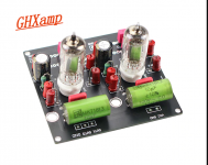
I did an experiment this evening. A while back I bought a few cheap valve stages from Aliexpress. One is in a postmans bag somewhere, but the other one landed here a while back. I originally bought these to try a lampizator type output stage on a CD player, but thought why not at least try it on this DAC. The module is like the one in the pic - its a 3a5 twin triode DHT and the arrangement is as a paralleled triode. I think its the same as was found in the driver stage of some Chinese valve amps.
Anyway, it hums, and is microphonic as you'd expect, but with a bit of B+ filtering and arranging the filament supply I was able to get it down to a reasonable level. I think I would need CCS on the cathode and a regulated anode supply, along with a dedicated filament bias system to get it completely quiet, but its interesting to see how it sounds. I used a 300R IV resistor which probably breaks all sorts of rules. It sounds pretty good. Its not as dynamic as EUVL's current mirror but its pretty nice I gotta say, very sweet, clean, good bass response if a little softer than the best, and a pretty glorious midrange. It doesn't offend in any way.
Not bad for 25 quid (once you have the parts to make up the PSU for it). Not sure if I'd recommend it to anyone - I think if you were going to do this, there would probably be better options out there, but I had it sitting there, wasn't that big a deal to do it, and its interesting to hear what a different output stage sounds like.
fran
Attachments
@fran
Have you measured what you have with the tube board in terms of voltage and impedance output compared to EUVLs current mirror?
Have you measured what you have with the tube board in terms of voltage and impedance output compared to EUVLs current mirror?
Nope!
I just stuck it on the end without thinking too much about it. The tube is meant to have a gain of 15x so headed for a IV resistor to roughly suit. I have 500r in there now. I focussed on getting hum to a low enough level for it not to be annoying. It sounds pretty good, but really this was just an experiment, see if it would work etc. Certainly all the advice seems to be to use filament bias and a regulated b+ with DHT valves, so if this was a runner I think that's what I'd be doing. Maybe in the future weeks. If the other 6n2 stage turns up I'll try that and compare, but I'm not sure what use my observations would be as they are not seriously enough implemented to really give anything but the broadest indication.
So if anyone is making progress with nautiboys boards, this type of output stage is certainly an option.
Will do - I've asked over in tubes forum about implementing this output stage, and heater wiring etc. There might be improvements possible.
OK, after several hours of trying things to sort out buzz etc, I have a solution.... use batteries! The tubes were made for batteries so its kinda logical. Its dead quiet with batteries, and everything has improved a bit. Its till microphonic, so even vibration from the transformer will set it going, so care is needed. But again, for the cost of a few D-cells and a 110V transformer for the B+ plus the board from Aliexpress, this is astonishingly good.
Lots of disadvantages compared to the current mirror stage, which would still be my go to option, but this sounds beautiful in a different way.
Lots of disadvantages compared to the current mirror stage, which would still be my go to option, but this sounds beautiful in a different way.
Fran,
do you have link the tube IV stage?
What is the input VDC?
So the output trafos are replaced with 10uF output caps?
do you have link the tube IV stage?
What is the input VDC?
So the output trafos are replaced with 10uF output caps?
@nano35 - search for 3a5 preamp
HiFi Audio 3A5 Valve Tube Preamp Bile Preamplifier Stereo Audio Tube Amplifier|Amplifier| - AliExpress
There are a few sellers, so you can shop around. 3a5 valves on their own run about 8-10usd each, so best to buy the kit with the valves included (unless you have them already). Circuit would be easy enough to breadboard up as well.
Input DC is over a wide enough range - 150-200VDC. No output transformers, just those 10uF caps, bypassed with smaller film ones. So there is some DC on the output as the B+ comes up, after about 5sec its down to nothing. I don't think its enough to damage a speaker, but it does mean a turn on noise.
Beware those valves are microphonic as hell - for example, I had jerry rigged up a large transformer with 130v secondary - it hums a bit (EI type) and vibrates. You can barely feel it with your fingers on the MDF base it is sitting on. But turn up the amp and you could hear it through the speakers. The whole circuit is also sensitive to RF/hum pickup. Although I don't have mine in a box, I found the orientation of that transformer was very important for the amount of hum pickup.
FYI - I still regard this as experimental only, things like having batteries is generally a pain, and the microphonics are a pain, so I can't recommend it people. But the sound is very nice indeed!!
- Home
- Source & Line
- Digital Line Level
- DAC AD1862: Almost THT, I2S input, NOS, R-2R