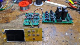
Same as jimk04 here, powered up fine, all voltages look good without chips in place, and also front end is connected. We'll insert the DAC chips tomorrow night and do the mains wiring. Then we can see if it plays ok!
I need to learn more about i2s for the future. Am I correct in thinking that while some DAC chips can accept a mck input, others don't (older ones like the 1862 here) and they run from the bck instead?
Fran
I need to learn more about i2s for the future. Am I correct in thinking that while some DAC chips can accept a mck input, others don't (older ones like the 1862 here) and they run from the bck instead?
Fran
Attachments
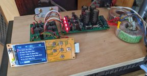
Got the DAC working this evening. Too early to give any impressions other than that it's working fine, nothing untoward on this stock build.
It will be interesting to compare output stages etc in time but first up I think it's wise to test and listen for a period.
A better test than the SD card player might have been the i2soverusb board as I could compare directly with the pass D1 clone (well it's inspired by rather than a clone), this would have allowed for more controlled comparison but maybe in good time.
Attachments
Dacs often benefit by being in a well shielded case so as to sound their best. 18-gauge steel, or 1/2" thick aluminum, with minimum holes for lowest EMI/RFI ingress. At least, they may need to be in a case when they are working well enough so that EMI/RFI ingress effects are not masked by bigger bigger problems 🙂
Last edited:
It 's maybe less important with old pcm diy dacs, cause others devices around are most of the time EMI shielded as well, and the circuitry of the dac less sensitive to the outside than DS dac chips ?! (I have no problem with my woded box old pcm dacs above my SMPS Chord amp for illustration... but that doesn't mean there is nothing... maybe I just don't hear it.
We have to remember shielding are most of the time not a protection for the device but a protection of the device for the others arounds (if one talks about the casing...)
But I put ferous wall inside the dac box between the circuitry and the power supply traffo... and cheap can tin on them for the placebo effect to sleep better 🙂 *
*:some digital front-ends work also better when shielded : high speed clocks, some stuffs like a Rasberry-Pi...
Last edited:
I may well case it in time to come, but having it loosely assembled on a breadboard is a practical solution for now while there are experiments underway. There may well be something going on in the high frequencies, but the unit is subjectively silent and nothing is above barely detectably warm.
I do exactly the same, my main DAC had no box because of three years of experiments. The Miro's dac of this thread has just a box for two weeks, as two others... I need to beginn to stop.😉
Unit has been on a soak test for >8 hrs, and all seems good. So I think these boards (last version for 1862, dip8, can be marked as good. Only thing missing is a label on the i2s inputs but they are easily enough figured out (and I think they were laid out to match a converter board from memory so a label might not be appropriate).
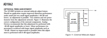
Miro/previous builders - can you point to a set of instructions for the MSB trim adjustment? I've seen this mentioned before but have never read into it.
fran
Miro/previous builders - can you point to a set of instructions for the MSB trim adjustment? I've seen this mentioned before but have never read into it.
fran
Fran,
The link in #1628 is the right one.
Unless you have a distortion analyser that can measure reliably to -120dB at 2mVrms.
If I were you I would just forget that for now and get the rest working.
And do some listening first.
🙂
Patrick
The link in #1628 is the right one.
Unless you have a distortion analyser that can measure reliably to -120dB at 2mVrms.
If I were you I would just forget that for now and get the rest working.
And do some listening first.
🙂
Patrick
Fran,
The link in #1628 is the right one.
Unless you have a distortion analyser that can measure reliably to -120dB at 2mVrms.
If I were you I would just forget that for now and get the rest working.
And do some listening first.
Yes, as Miro said - it is not a simple task to adjust this from what I have read so far. Its good to know.
Fran
Congrats Fran on getting the PSU2 and Dac boards successfully powered up and singing. Mine is still on a wood plank, LOL!! Which opamp do you have installed now? I like your display, what USB to I2S converter are you using?
The build is completely stock - so its the LM6171 in sockets for now. Haven't even looked at anything else yet!! Although I have ideas!!
The player is a simple SD card player from aliexpress - STM based....
The player is a simple SD card player from aliexpress - STM based....
Well done Fran! So far it looks good and hopefully everything will work.
Thanks for sharing 🙂
Thanks for sharing 🙂
... so do you like what you hear, as now it's working ?
@Patrick (EUVL) : did you populate the Miro's board and like it ? It would be very appreciated if you can said to us the oaps yu liked the most and if you hacked the I/V stage with your circuitry to testimonie about the differences you hear. 🙂
@Patrick (EUVL) : did you populate the Miro's board and like it ? It would be very appreciated if you can said to us the oaps yu liked the most and if you hacked the I/V stage with your circuitry to testimonie about the differences you hear. 🙂
Last edited:
Yep, its coming along very nicely. I only have subjectively compared it to the D1 clone I have, and that is running from an i2soverusb card rather than the SD card player, which usually has the edge on usb in my past experience.
It compares very well. I have to be a little careful because it is a shade higher output than the D1, and it is very easy to fool the ears with that. Its very balanced bottom to top, plenty of bass there for sure. There is good soundstage depth and detail too - perhaps I've heard more detail from other DACs but sometimes that results in some listening fatigue after a while. Initially its "exciting" maybe as your attention is drawn to things, but after a while you are happy to turn it off. I don't get that sense from this, although it is early days yet. The other thing that's noticeable are the dynamics, snap of percussion, or pluck of strings stand out.
I'm not hearing many negatives with it. I think its a little harder sounding on first power up, maybe it rounds out a little after being on for a short while, but I cannot be definitive about that, and it could well just be psycho stuff (sitting down for the first time, vs 20mins later when more relaxed etc).
I think there are lots of possibilities here. I wonder about separate power supplies for the various stages, about output stages too, even valve output stages (which I am hoping to do with a second build). As more people build this, and report back the results of their experiments we will all benefit!!
Something else I wanted to mention in passing in case anyone else is does the same thing as me. So I temporarily piggy backed the SD card player on the 5v rail, putting extra draw on it. This of course caused the reg to get uncomfortably hot so this was always going to be a temporary job. Anyway, at turn off, the +5v rail collapsed more slowly as a result and I noticed a significant turn off thump as a result. I don't think it would harm speakers, but if you had headphones it might do damage.
I've since cleaned up my act, and given the SD card player its own supply as is proper anyway so there is only the tiniest of soft thumps now at turn off. I only mention this as I imagine some people might use the +5v rail to run an xmos card or something.
I've since cleaned up my act, and given the SD card player its own supply as is proper anyway so there is only the tiniest of soft thumps now at turn off. I only mention this as I imagine some people might use the +5v rail to run an xmos card or something.

Interesting feedback Fran, thanks for sharing your listening experiences.
Also, for your comments on sharing the 5V power supply - I am toying with powering the clean side of the JLSounds board with it so will watchful now.
I think I'll omit the tweaking potentiometers too.
Ray
Also, for your comments on sharing the 5V power supply - I am toying with powering the clean side of the JLSounds board with it so will watchful now.
I think I'll omit the tweaking potentiometers too.
Ray
Ray - I just tapped into the same transformer secondary, but used a separate PSU that puts out 5V for the player. The i2soverusb needs two supplies and probably deserves its own Tx with dual secondaries, and the dirty side pulls a fair bit of current - any reg here will need some heatsinking. I have used one of those LT3042 boards from aliexpress to power the clock side successfully but the "dirty" side needs a bit more juice.
- Home
- Source & Line
- Digital Line Level
- DAC AD1862: Almost THT, I2S input, NOS, R-2R