>>are there any downsides of using op-amp (output) in this DAC and than going straight to op-amp (input) in my_ref amplifier
You can connect it straight with no worries 🙂
Is it this schematic? link
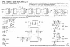
C13 input capacitors in the amplifier can have significant impact on the amplifier sound (should be high quality audio capacitors, like PP type). This DAC with a good opamp in the I/V has normally zero offest on the output (or a few mV) and therefore you can try to short C13 capacitors and listen to a difference in the sound quality.
C9 use also a high quality audio capacitor (nichicon UFG or UKZ serie).
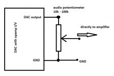
You can also connect a high quality audio potentiomter directly after DAC with no worries (with opamp I/V).
You can connect it straight with no worries 🙂
Is it this schematic? link
C13 input capacitors in the amplifier can have significant impact on the amplifier sound (should be high quality audio capacitors, like PP type). This DAC with a good opamp in the I/V has normally zero offest on the output (or a few mV) and therefore you can try to short C13 capacitors and listen to a difference in the sound quality.
C9 use also a high quality audio capacitor (nichicon UFG or UKZ serie).
You can also connect a high quality audio potentiomter directly after DAC with no worries (with opamp I/V).
Attachments
Thanks Miro, yes for C13 I will use suggested auricap XO series. And for C9 I am going with Elna Cerafine. For now for volume control I am using arduino based LDR so will see how things work together. So my mind is at peace for now. Just waiting parts from mouser to start building the amp. Than it is back to tweaking this DAC that finally gets the amp it deserves...
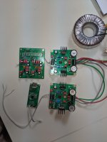
I found I made an error with my JLSounds stacking AD1862 boards so I made the correction and took the opportunity to make some other improvements - I ordered some replacement prototype PCBs from JLC today.
Hi guys, long time lurker here.
I have been following this thread since the start and have now assembled 2 boards resulting in the same "problem" on both, and asking here for any thoughts on the issue I am seeing.
After assembly, all voltages measure correct with all boards connected, that is the p.s. boards and also the I2s board. However, it seems as soon as I put in a USB cable connected to a PC, the +5v rail loads up and measures less than 5. When the USB is removed the issue is remains. I have tracked it down to the "buffer" area of the board, by removing J9, I reckon the 74HCT164D chips are damaged when connecting the USB. When I remove these chips, the +5v is correct again. Just by soldering in the first chip IC1, exactly the same happens after plugging in a USB.
Could it be the way I have my p.s. wired, that is both 12v & 5v pcb's sharing the one transformer secondary, or could I have a bad USB to Is2 board.
Any thought appreciated.
Attachments
Why NOS DAC is better, or maybe not ?
From Mr. NOS himself :
TNT-Audio inter.views Kusunoki San [English]
"The non-oversampling DACs have distinctive tonal quality, but I couldn't figure out the reasons in the early stages.
I found the answer after listening to a DAC using eight DAC ICs to bring about 8-times oversampling without digital filter.
The DAC's sound clearly indicated that oversampling was not the culprit of sound degrading, but the real offender was the digital filter.
Digital filters cut off signals beyond 20kHz with a very steep curve, but needs around 2msec of time to calculate the enormous data.
I think this is the reason of "diffusion of sound coherence", the characteristic tonal quality of the oversampling DAC."
So it depends on your digital filter.
Digital filters have progressed quite a lot since 2002.
Cheers,
Patrick
Hi @speakes1
Measure AC voltages on secondaries here:
AC voltages ... voltmeter should indicate 2x AC voltage. If it is less (around zero), switch 2 wires between on one secondary (green with brown).
We will solve the issue 🙂
Transformer secondaries can be shared.Could it be the way I have my p.s. wired, that is both 12v & 5v pcb's sharing the one transformer secondary, or could I have a bad USB to Is2 board.
Measure AC voltages on secondaries here:
AC voltages ... voltmeter should indicate 2x AC voltage. If it is less (around zero), switch 2 wires between on one secondary (green with brown).
Do you mean the +5V rail from the LM317 power supply? Let J9 connected and measure the current consumption on the +5V rail (without and then with I2S board connected)....
... as soon as I put in a USB cable connected to a PC, the +5v rail loads up and measures less than 5. When the USB is removed the issue is remains. I have tracked it down to the "buffer" area of the board, by removing J9, I reckon the 74HCT164D chips are damaged when connecting the USB.
We will solve the issue 🙂
Hi I would very much like to hear this DAC with AD1862 chip. I have heard AD1865.
Can anybody please explain the sound quality and musicality of this AD1862 compared to AD1865?
Also I am very much interested to buy DAC with a single ended tube output stage like Audio Note DAC . I am very new to DIY and this seems to be complicated project for a beginner.
THank you.
Can anybody please explain the sound quality and musicality of this AD1862 compared to AD1865?
Also I am very much interested to buy DAC with a single ended tube output stage like Audio Note DAC . I am very new to DIY and this seems to be complicated project for a beginner.
THank you.
Ah. I think I could contribute here.
Ripster, the short answer is : unfortunately, not a good idea (just to eliminate one opamp from the 'picture')
Each opamp does it's own task. Both (I/V conversion & feedback loop control) tasks are resource intensive. They need all the best from the dedicated opamp. The best result will be obtained if the actual opamp is left to engage in one, dedicated task..
(the I/V opamp on the Miro board output is not 'just' a buffer; the opamp in the Myref board is much more than an input buffer- it is heart and soul of the full circuit..)
Hey I have a question for more knowledgeable people around here... I will start building new amplifier (My_ref) now that the GB is over and I received PCBs and I have a question regarding op-amps since my_ref uses op-amp on input stage. So I was just wondering and have no clue where to start looking for answers, first one that pops in my mind is are there any downsides of using op-amp (output) in this DAC and than going straight to op-amp (input) in my_ref amplifier. I know if this two were a commercial product you would just connect the two and listen. But since this is DIY forum I am just interested if there would be any other (better) way of doing this or some other things to look for, like same or diferent op-amps, or maybe no op-amp in DAC or It will be just fine as is. 😕🙂 Thanks
Last edited:
Hi @speakes1
Transformer secondaries can be shared.
Measure AC voltages on secondaries here:
AC voltages ... voltmeter should indicate 2x AC voltage. If it is less (around zero), switch 2 wires between on one secondary (green with brown).
All this tested as should
[/QUOTE]Do you mean the +5V rail from the LM317 power supply? Let J9 connected and measure the current consumption on the +5V rail (without and then with I2S board connected).[/QUOTE]
Yes, +5v rail from LM317 power supply
1 x in board 74HC164D and measured 0.001mA pre Is2 board and 0.105mA with Is2 board
2 x in board 74HC164D and measured 0.001mA pre Is2 baord and 0.210mA with Is2 board
Also was measuring 5v from the LM317 p.s.
Things were going well, I even thought about inserting the DAC and Op-amp to have a listen to the RHS, but prior, I power cycled several times to see if I could replicate the earlier fault, and the inevitable happened - smoke escaped out of both registers, and I know that the smoke is what makes it work (I must re-stock on the smoke in a can) lol..
Seems like I have quite a bit of trouble shooting to do now..
Anyway miro1360 thanks for your time and I'll let you know how I go.
Last edited:
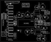
AD1865 ... the same principle
Not having AD1865 DAC in the collection?
Here is one ... the same PCB changed for AD1865 DAC.
It is tested by @Vunce.
Power supplies are slightly different!
analog part: +5VA, -5VA
digital part: +5VD
Have DIY fun 🙂
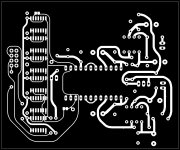
Not having AD1865 DAC in the collection?
Here is one ... the same PCB changed for AD1865 DAC.
It is tested by @Vunce.
Power supplies are slightly different!
analog part: +5VA, -5VA
digital part: +5VD
Have DIY fun 🙂
Attachments
Thanks for another “Toy” to fiddle with, Miro 😀
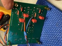
This new board works perfectly, I loaded it with Panasonic FR and Wima MKP2 caps. Takman carbon 2K2 at R8,9 and PRP 68R at R10,12. Components are place on both side of board again to clear room for opamp and I/V tweaking. Listening now with Burson opamps.
The double row 6 position header is awkward to work with, glad you modified it so the GND pad is inline. Now a single row, 4 position Molex KK type header will work. Also the addition of SMD pads for the bypass film caps around the opamps is a nice feature 😉
For the first tweak, I added a TPS7A4700 +5v regulator right at the AD1865 digital supply pin.
My AD1865 chip comes from a past Rochester GB, they are the only place I know of that still has genuine goods.....Maybe Paddy G. will start a new GB if there is enough interest 😀
Thank you for sharing another cool project Miro... keep them coming 😉
Attachments


Thanks Vunce for your detailed description. The adjustments are added on your tips 🙂
No worries, DIY things increase over time 😀
No worries, DIY things increase over time 😀
Thanks Vunce for your detailed description. The adjustments are added on your tips 🙂
No worries, DIY things increase over time 😀
Did you compare the onboard V-out option?
Hmm... not yet NB.
But, I assumed (probably bad to do), Iout is the way to get best sound from these Dac chips.
I have 4 of these boards available if anyone is interested, probably best to be located in the States so I can send it in a regular letter envelope. Just PM me.
Cheers!
But, I assumed (probably bad to do), Iout is the way to get best sound from these Dac chips.
I have 4 of these boards available if anyone is interested, probably best to be located in the States so I can send it in a regular letter envelope. Just PM me.
Cheers!
Nice work Vunce!Thanks for another “Toy” to fiddle with, Miro 😀
This new board works perfectly, I loaded it with Panasonic FR and Wima MKP2 caps. Takman carbon 2K2 at R8,9 and PRP 68R at R10,12. Components are place on both side of board again to clear room for opamp and I/V tweaking. Listening now with Burson opamps.
The double row 6 position header is awkward to work with, glad you modified it so the GND pad is inline. Now a single row, 4 position Molex KK type header will work. Also the addition of SMD pads for the bypass film caps around the opamps is a nice feature 😉
For the first tweak, I added a TPS7A4700 +5v regulator right at the AD1865 digital supply pin.
My AD1865 chip comes from a past Rochester GB, they are the only place I know of that still has genuine goods.....Maybe Paddy G. will start a new GB if there is enough interest 😀
Thank you for sharing another cool project Miro... keep them coming 😉
Can you compare the sound of the two ad chips with the same i/v?
Hi Pistollero,
I could do that.
It would be most easiest/fastest with just opamp I/V. The other options I use require a bit more time to set up.
Rather than compare against each other, I’d be more likely to compare against the other AD1865 DAC’s in my stable.
I could do that.
It would be most easiest/fastest with just opamp I/V. The other options I use require a bit more time to set up.
Rather than compare against each other, I’d be more likely to compare against the other AD1865 DAC’s in my stable.
My AD1865 chip comes from a past Rochester GB, they are the only place I know of that still has genuine goods.....Maybe Paddy G. will start a new GB if there is enough interest 😀
Thank you for sharing another cool project Miro... keep them coming 😉
Aieee - another project? Dang. The 1862 got me to sell my turntable, wonder what'll happen with the 1865?
I wasn't going to do more GBs but could do one for 1865s if someone can generate enough interest - Rochester's minimum for AD1865N is 12, for AD1862N-J is 10.

- Home
- Source & Line
- Digital Line Level
- DAC AD1862: Almost THT, I2S input, NOS, R-2R