NR caps?This was something I trying to improve about my AD1862 dac for a while now, unfortunately though it seems to be a trait of the AD1862 that cant really be improved much.
experimenting with the NR caps may your best bet
intervention in the I/V section causes major improvements (for any DAC), even changing to another opamp will do a lot
... for a deeper bass a circuitry with bass boost technique can be added, any coloration of the sound can be created 🙂
you can try this passive bass boost:
R10 = resistor 2k2
C37 = foil capacitor 470n + resistor 1k5 connected in series
for lower bass frequency increase the foil capacitor value
for stronger bass boost decrease the 1k5 resistor value
Thks for the help.intervention in the I/V section causes major improvements (for any DAC), even changing to another opamp will do a lot
... for a deeper bass a circuitry with bass boost technique can be added, any coloration of the sound can be created 🙂
you can try this passive bass boost:
R10 = resistor 2k2
C37 = foil capacitor 470n + resistor 1k5 connected in series
for lower bass frequency increase the foil capacitor value
for stronger bass boost decrease the 1k5 resistor value
If the bass are round this is there is a problem with the regs or the cas or the opamp... AD1862 has not round bass when correctly setuped !
As for the TI resistor, was tested to death and people often preered some others : I advice to test it side to side to a vishay precision group in the list I provided in a post above.
For the TPS7A : first make an experience with the main cap (2200 or 3300 uF most of the time that feed the reg) to solve the bass ? Which cap have you for the 12 V ?
Nano35,
Good to see you here too! Are you planning to connect to the RPi via I2S?
My original plan is to connect AD1862 from RPI+FIFOPi but
my case is quite full with 3 sets of LPS for both RPI and FIFOPI.
There is not enough room for the extra 2 sets of dual LPS and an extra transformer.
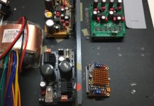
So I will build the AD1862 in a new case using Singxer F1.
Photo shows part arrangement and ready to drill holes.
I am a slow DIYer 😀
Attachments
That doesn"t man it will be worse with the Singer... it may be better despite the FifoPi....Rpi stays a limitation whatever you put after ! So the Singer is not a bad choice...
RPI and how you must work wirh it -vertical stack- is bad or audio and needs expensive hat to get better and even so it's not perfect.
The ad1862 is a PCM board and many good usbtoI2S board will give good results. If you have already an Rpi and a Fifo, don't get crazy but if you haven't and need just an USB input, well a good enough USB to I2S card already advised here will be as good IF not better - but if feeded from a laptop or little computer you will still need an USB isolator between it and the usb board; cost 20 to 30 euros. of course don't take an USBto I2S to feed it from the usb outputt of an Rpi : it will be the worst solution !
The ad1862 is a PCM board and many good usbtoI2S board will give good results. If you have already an Rpi and a Fifo, don't get crazy but if you haven't and need just an USB input, well a good enough USB to I2S card already advised here will be as good IF not better - but if feeded from a laptop or little computer you will still need an USB isolator between it and the usb board; cost 20 to 30 euros. of course don't take an USBto I2S to feed it from the usb outputt of an Rpi : it will be the worst solution !
Anyone using lower values on nr caps?
10uf +1uf
22uf+2.2uf
??
Im using smaller film caps (1+10uf) in parallel with bigger lytics (47+470uf)
Any other I2S source better than rpi?
Can you recommend or share experience
Arylic seems a good one
Member
Joined 2006
RPI and how you must work wirh it -vertical stack- is bad or audio and needs expensive hat to get better and even so it's not perfect. ... well a good enough USB to I2S card already advised here will be as good IF not better...
I am curious too.. wondered how well they fare: Pi3- fifopi (i2s) vs a good USB to i2s converter (like, JLsound)..
BTW, anyone compared JLsound to Audial usb to PCM? (Sorry OT a bit)
I know a guy that have them all and he prefers the Pedja's to the JLSounds !
Don't remember if he tried with the AYA 2 and the USB pedja board or the all in one AYA 4 !
And he prefered the JLSOunds to the FifoPi...
Don't remember if he tried with the AYA 2 and the USB pedja board or the all in one AYA 4 !
And he prefered the JLSOunds to the FifoPi...
Member
Joined 2006
It isn't , you can just get the populated one though... not diy raw pcb ! And it is costy to get the full populated halas ! So I haven't tried it - mine is full IanCanada and I find it without the fifo quite good as well in simple I2S with the Wave I/O i2s to usb from Luckit !
Btw does your Audial model 3 have opa861 for I/V or is it full discrete after the TDA ?
I think my Miro's AD1862 will be ready end of August !
Btw does your Audial model 3 have opa861 for I/V or is it full discrete after the TDA ?
I think my Miro's AD1862 will be ready end of August !
Last edited:
Member
Joined 2006
Great, Miro's AD1862 certainly is a good one, looking forward to hearing your impression! 😀
And..yeah..its the discrete circuit, like the Painkiller's as you stated...🙂
And..yeah..its the discrete circuit, like the Painkiller's as you stated...🙂
Thank you, I had a doubt and believed he was just used discrete on the buffer but not the I/V... I surmise the discrete is made of discrete Jfet... BA245A or more probably SK170 😀
do the measurement if possible, how much pS or nS do you consider as the limit for 16bit/44.1kHz R2R with direct latch, vs. delta-sigma?
Hi miro - seems I was a little hasty in offering to make that measurement. I've had a lot of headaches trying to get PCM2706 to work reliably on my interface design. Eventually I gave up as a chip would work fine one day but not enumerate the next - I can only assume that the chips I was sold were sub-standard (aka fakes). Jitter measurements on fake chips aren't very useful. I've since changed over to CM102S which is a much simpler chip and only has S/PDIF output but if you're interested in jitter measurements for that I'll give it go.
On your question I haven't got a number really and my ears aren't very sensitive to jitter. My wife does better in that regard. S-D DACs aren't uniformly sensitive to jitter they have different ways to mitigate the effect - using switched-cap tech (as AKM do on many DACs) is one way to go.
the jitter requirement has to be more demanding with oversampling (or with higher audio frequency), right?
Higher output frequency of a DAC degrades more with the same jitter number yes. Which is the primary reason S-D is sensitive - they output a ton of high frequency noise which can fold-back into the audio band under the influence of jitter.
- Home
- Source & Line
- Digital Line Level
- DAC AD1862: Almost THT, I2S input, NOS, R-2R