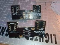
PCM1702-K in operation. 
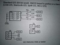
Shift registers are HCT, but at the start, 1702 refused to work. Then @Brijac reminded me that there might be a fault on the GND pins of the I2S connector, like on the PCM63 board, and there really is. I had to connect pin 8 to pin 7 because pin 8 is the GND of my I2S cable. Without it, it just crumbles. Above it says GND on the board for pin 8, but below it is not connected, I missed it.🙄
Shift registers are HCT, but at the start, 1702 refused to work. Then @Brijac reminded me that there might be a fault on the GND pins of the I2S connector, like on the PCM63 board, and there really is. I had to connect pin 8 to pin 7 because pin 8 is the GND of my I2S cable. Without it, it just crumbles. Above it says GND on the board for pin 8, but below it is not connected, I missed it.🙄
Attachments


Quick question. I have a streamer that is optimzed for I2S over HDMI (PSaudio pinout). Would something like the HDMI receiver from The WellAudio or Audio-GD work to feed I2S to the DAC board development by Miro1360?
https://www.thewellaudio.com/twsafb-rx/
http://audio-gd.com/Pro/diy/I2Skits/I2SEN.htm
Cheers -
https://www.thewellaudio.com/twsafb-rx/
http://audio-gd.com/Pro/diy/I2Skits/I2SEN.htm
Cheers -
Ian Canada also sells a HDMI receiver that could work for this DAC. It is less than $30 plus shipping.
Thanks for the swift reply. I was unaware of Ian's part and it looks like it would work well.
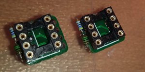
Dual to single mono adapter works as expected as well. For those that really want to minimize every single bit of crosstalk and reduce heat of dual chips.

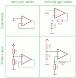
The practice is to connect both unused inputs together and to the GND. Or in this case to the + input of the active OPA because it is already on GND in this schematic. The output of the unused OPA should float, unconnected. As I've never tried this, I can't say it's necessary.
Feedback
People also search for
Feedback
People also search for
Can be adjusted on this pcb 🙂 I'll make new one with such adjustment as default with. One thing though, article writes about non inverting opa configuration, says nothing about inverting? Consider it the same?
Adjusted as per TI sheet, and sound wise i hear no difference. Temperature wise, same. So no oscillations, or audible noise.
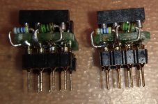
But doesn't hurt, so as seen in the picture it is easy to configure.

And again, no real need for this, just use dual to dual single adapter and save money 🙂 It can be even more benefitial if there are fast opamps used due to much better decoupling (that adapter has dcpl capacitors at voltage pins).
But doesn't hurt, so as seen in the picture it is easy to configure.
And again, no real need for this, just use dual to dual single adapter and save money 🙂 It can be even more benefitial if there are fast opamps used due to much better decoupling (that adapter has dcpl capacitors at voltage pins).
I was fiddling with these adapters last night. For the Muses 02 and unused half of it I chose a two-resistor scheme, so I can try some other non-unity gain stable OPA. I had some of these miniature 4k7 and 1k5 on hand, that should be safe for any OPA (gain 3.13). For the GND point I used the +input of the active half (pin 3). @Brijac tried unity stable schematics, no resistors. I hope I can try it all tonight.
Attachments
For now, I'd say it's positioned between the AD1865N-K and the PCM63P-K. I don't have too much bass like we heard on some other samples. Now comes the OPA rolling to see what suits him best. I have problems with lack of time, and I have a lot to try. 🙄@NIXIE62 we want details and listening impressions with PCM1702
The first question is whether crosstalk can be heard...you decide. You heard how Meses02 plays on the motherboard and where it goes in terms of quality. Another question is whether the improvement is the same on the DAC.😆I have problems with lack of time
I won't know until I try, and I ordered 1k5 and 4k7 SMD resistors for that little adapter. It will be much more elegant. Practically invisible.
hello, tell me pleasehttps://www.hificollective.co.uk/wire/mundorf-silvergold-wire-110sgw.html
I put this wire as I2S - holy s*it how much better this is now. - I soldered directly to the resistors😎
View attachment 1177751
where can i buy this board?
Or where can I get a file for printing (pcb) of such a board
@NikNet the Gerber files are here:
https://www.diyaudio.com/community/...s-input-nos-r-2r.354078/page-209#post-7049224
https://www.diyaudio.com/community/...s-input-nos-r-2r.354078/page-209#post-7049224
V1.1 done 😁 In case of unity gain opamp used, no resistors are needed, only the pads of first one from top need to be bridged. In case of non unity gain opamps, both resistor slots need to be filled with required value resistor (by default 10kohm). These should fit all cases in regards to miros dacs, as IN+ is shorted to ground.

As usual, gerbers will be available when it's tested/tripple checked.
As usual, gerbers will be available when it's tested/tripple checked.
- Home
- Source & Line
- Digital Line Level
- DAC AD1862: Almost THT, I2S input, NOS, R-2R