FWIW it was for having multiple accounts. I ordered 4 from him and they arrived ok. So did several others who've received theirs. But what he was doing was a one off so it's academic.If i remember, latest big purchase that was up for sale, the user was banned.

Glad it worked out fine 
I think someone from US would be the best candidate for next order. I cannot even import it here without hiring company to represent me due to order having over 4 pieces, since our customs here utilize system from the 70's..... And that would double the price of them.
I think someone from US would be the best candidate for next order. I cannot even import it here without hiring company to represent me due to order having over 4 pieces, since our customs here utilize system from the 70's..... And that would double the price of them.
there was another one after this one, but it did not materialise due to Rochester's policy. In the end the GB starter bought off from ebay.If i remember, latest big purchase that was up for sale, the user was banned.
https://www.diyaudio.com/community/threads/ad1862n-chips-n-dip-for-sale.394960/#post-7258730
I know that PSU 1 and PSU 2 boards work well for running the Miro dac. Since if I order using the gerbers I will get more boards than the one or two I need, I was wondering what else I could use them for. I have applications for +/- 9V and +/- 15V uses. What sort of loadings can the PSU boards accommodate? Can the PSU board components be modified to change the output voltages?
These boards would make a nice dual mono power supply for a preamplifier. Look over the regulator IC datasheets. With the appropriate transformer secondary voltage, any bipolar DC output up to +/-24V and 1A (with heatsinking) would be possible. Just be sure your capacitors are rated for higher voltage than the raw DC after rectification.
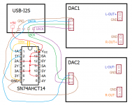
You can make the multichannel DAC even now from the available PCBs. The PCBs can be stacked to save some space 😉 See the attached picture how to connect one stereo balanced DAC.... I wanted to ask, maybe in your plans there is a desire to design at least one multi-channel DAC, for 8 channels? With this trouble at present, there are practically no good multi-channel DACs available on the R2R for self-assembly. It would be great for cars and cinemas. At least on AD1865 (several channels are possible in dual mode, one chip per channel for better quality))). ...
I didn't find a good way to route it all on one PCB in order to save space or gain other advantages. The only saved place would be possible with all in SMD, including PSU. In addition, such a large device is more difficult to repair and more difficult to modify ...).
Attachments
The tda1541 PSU is a good one too as it gives you several different rails using 78/79xx regs. You can populate whatever voltage reg you like in there, you don't have to follow the silkscreen. Will be limited by the current that the reg can handle and the heatsinking you provide.I know that PSU 1 and PSU 2 boards work well for running the Miro dac. Since if I order using the gerbers I will get more boards than the one or two I need, I was wondering what else I could use them for. I have applications for +/- 9V and +/- 15V uses. What sort of loadings can the PSU boards accommodate? Can the PSU board components be modified to change the output voltages?
Are solid polymer caps good for any specific areas of applications on the DAC boards here? I understand that they can have higher leakage current than electrolytics but lower esr.
Polymer caps are useful for local decoupling of DAC power supply pins though beware that if that cap's being fed by a 3pin regulator the low ESR of a polymer may well endanger its stability. If so, a series L would be called for.
The high leakage of polymers precludes their use for decoupling references, servos and BPO outputs of DAC chips.
The high leakage of polymers precludes their use for decoupling references, servos and BPO outputs of DAC chips.
Hey guys,JLSounds I2S has galvanic isolation between input and output (separated GND).
First try to power the isolated part (output) from an internal regulator.
This isolated output must be powered (either from internal regulator, or from external (+5V DAC)), connect the internal regulator:
Connect H1:1 with H3:17 (VDD)
Connect H1:2 with H3:2 (GND)
Your second picture is not the reference, it is reference only for direct connection without the glue logic (see my post #538) ...
The reference for DAC with glue logic still be this (without R1):
I2SoverUSB BCLK (H3:11) —> BCK Dac
I2SoverUSB DATA (H3:13) —> DATA Dac
I2SoverUSB LR (H3:15) ——> LRCK Dac
GND (H3:14...) ——> GND
But now in manual is section with different I2S protocols, do the following configuration from the page 5:
"JLsounds AK4396 DAC board I2S mode (old I2SoverUSB board)"
J3:Open, J4:Open, B1:Close, B2:Close, B3:Close, B5:Open
... this should be the standard I2S mode in 64-bit frame
If that worked, you can try to power the isolated part (H3:17 and H3:2) from +5V DAC board 🙂
do you know if this also would work for JLsounds viii + AD1862 if I power JLsounds from USB?
Does anyone have schema or the photo how to connect them?
Or shall I just follow the PDF from JLsounds?
Thanks!
Thank you very much for sharing this knowledge. @abraxalitoPolymer caps are useful for local decoupling of DAC power supply pins though beware that if that cap's being fed by a 3pin regulator the low ESR of a polymer may well endanger its stability. If so, a series L would be called for.
The high leakage of polymers precludes their use for decoupling references, servos and BPO outputs of DAC chips.
Yes, it will work. Follow pdf.
Hey guys,
do you know if this also would work for JLsounds viii + AD1862 if I power JLsounds from USB?
Does anyone have schema or the photo how to connect them?
Or shall I just follow the PDF from JLsounds?
Thanks!
I'm wondering if anyone can help me out with a question about using a scope. Currently, my scope is showing 11.7V and a flat line on both outputs. I'm not sure if this is expected or if I might be measuring something incorrectly. I apologize for the newbie question, but any insights or guidance would be much appreciated.
Thank you!
Thank you!
Attachments
Hi Vavilen,
I'm sure one of the more knowledgeable will jump in here, but as Nixie said it looks like a problem but you didn't give much information.
Since you don't know your scope well, I would start simple and use your volt meter to test DC output at the DAC outputs. Measure both the left and the right and report back. If you volt meter is reading close to 0v, it should be in the mV range, then you are okay, if not your circuit has a problem that we need to figure out, not your scope settings.
We can give you more hints on how to set up your scope once you have a verified circuit to test.
Let us know,
G
I'm wondering if anyone can help me out with a question about using a scope. Currently, my scope is showing 11.7V and a flat line on both outputs. I'm not sure if this is expected or if I might be measuring something incorrectly. I apologize for the newbie question, but any insights or guidance would be much appreciated.
Thank you!
The main question is, are you measuring a working DAC or not working?
V1 and V2 (yellow and blue lines) are probably only triggers and not the signal wave 🤔
Some signal should play through that DAC during the measurement ... program Visual Analyzer is very good freeware, it has the Waveform generator, so you can conveniently run frequencies through the DAC and measure it with an oscilloscope.
It is best to watch some oscilloscope tutorials on youtube:
Attachments

What is working and what is not warking DAC?are you measuring a working DAC or not working?
- Home
- Source & Line
- Digital Line Level
- DAC AD1862: Almost THT, I2S input, NOS, R-2R