I do not think for the tda1540... i writed too much fastly.
Looking forward to know about the difference with JLSOUNDS or registers...
Looking forward to know about the difference with JLSOUNDS or registers...
Unfortunately not, you will need the CPLD converter 🙂JLsounds to Miro 1541 in simultaneous mode. Will it work on 1540 too?

Has someone tested the stopped clock version form this post? I have the version with the error and I have given up on repairing it.
I am using the I2SoverUSB, and I am not needing the logic part, but the linked version has the ground plane separation. Initially I did not go with the stacked version, because I was a afraid of noise, anyone noticed any downside (if having compared)?
I am using the I2SoverUSB, and I am not needing the logic part, but the linked version has the ground plane separation. Initially I did not go with the stacked version, because I was a afraid of noise, anyone noticed any downside (if having compared)?
Thanks Miro, realised that is not a sound approach, will look into other options.You can add unity gain buffer with passive I/V resistor to the GND (as you specified) ... but this approach does not have high reputation 🙂
Has anyone built Miro's DC protection board from post#5697?
If so, is there timed delay before signal is passed when first powered on?
If so, is there timed delay before signal is passed when first powered on?
i am waiting for the relays and those small transistors from Farnell to complete the dc protection board. Just curious, how sensitive is the dc protection? what level of dc offset will trigger on the protection?
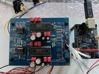
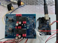
Here is my PCM63 DAC. Sounds great! Thanks @miro1360!
My USB interface is I2SoverUSB v.III of JLSounds, in pcm63 mode without shift registers on the board. Op amps are LM6171 with a separate +/-12 volt supply. Everything around them is mounted on the underside. I have already tested with AD797 as well.
My USB interface is I2SoverUSB v.III of JLSounds, in pcm63 mode without shift registers on the board. Op amps are LM6171 with a separate +/-12 volt supply. Everything around them is mounted on the underside. I have already tested with AD797 as well.
Attachments

Today I am baffled by the problem of the dc protection board.. LED does not turn on when powered up. Thought maybe it needs an input load. So connected to Dac output but the behaviour is the same. Measured output from TDA1541, DC offset reads around 4mV or so on both channels.
So I made another board with my spare parts and the same behaviour happened. However this one worked for two seconds after powered on for a few seconds. The relay clicked, led lighted up for a second but another click and led is off again.
So the DC protection is always triggered ( led not lighted up) . All transistors, relays and op amp are from good source Farnell. Caps and resistors and 1n4148 are from local retailer.
Any suggestions, advice or ideas please.
Last edited:
I wish to thank Miro for his help, the dc protection is working flawlessly now in my Miro TDA1541 DAC. In order for do a proper test, the DC protection board need to be connected to the DAC/preamp outputs. If you are doing a test on just the dc protection board without a load at its input, you will not be able to turn on the board shortly after you power down and power up because the circuit is still in protection mode. This is due to C1 and C2 still holding charge. If you wish to test the protection board without connecting to a source load, you can do it with the L-IN and R-IN shorted to ground and you will be able test its function properly.
Thanks again Miro.
Thanks again Miro.
- Home
- Source & Line
- Digital Line Level
- DAC AD1862: Almost THT, I2S input, NOS, R-2R