Hey guys!
Just wanted to drop in and say thanks a ton for all the help and answers you gave me. Seriously, you guys rock!
So, it turns out that V1 and V2 weren't actual voltages, but just scales for measuring voltage amplitude. My bad for not getting that straight away. 🤦♂️
Anyway, my voltage is currently sitting at around 20mV with some teeny pulsations.
Unfortunately, still no sound yet, but at least I'm not getting that freaky 11.7V anymore!
Thank you!

Working = functional and opposite 😊What is working and what is not warking DAC?
Great Vavilen,Anyway, my voltage is currently sitting at around 20mV with some teeny pulsations.
Do take a look at Miro's suggested video or others like it.
How are you feeding a signal to the DAC? Playing music or sending a test tone? Vout of the DAC for your scope to read will be dependent on how loud you are playing at the input. Without an amp or speakers hooked up it is generally okay to set at full volume. Now based on that you need to set your scope at a resonable range, let's say 1V/div., and you should see some signal on your scope. Again if having trouble you can always set your volt meter to AC and get a reading from there, but most volt meters will only read RMS so your scope will see peak, don't expect these number to match.
Report back here what you find. If you are sending a strong digital signal to the DAC but not getting anything out it is likely you have made a mistake solding up the PCB or your I2S signal is not getting to the DAC for some reason.
G
Important update correction for DAC PCM58 from the post #4639
@abraxalito find out, that the polarized capacitor on pin 15 is rotated incorrectly in datasheet and in my schematic. PCM58 update #4
I confirmed his finding with service manuals of 2 different players (pioneer PD-71, sony CDP-970).
Therefore all of you who built my DAC, please rotate this capacitor correctly (C45, C46 capacitors +pin is going on DAC pin 15).
Last edited:
We'll spotted Richard. Thanks for the heads up Miro
@chi0001Important update correction for DAC PCM58 from the post #4639
@abraxalito find out, that the polarized capacitor on pin 15 is rotated incorrectly in datasheet and in my schematic. PCM58 update #4
I confirmed his finding with service manuals of 2 different players (pioneer PD-71, sony CDP-970).
Therefore all of you who built my DAC, please rotate this capacitor correctly (C45, C46 capacitors +pin is going on DAC pin 15).
Hi guys,
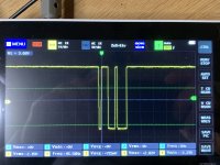
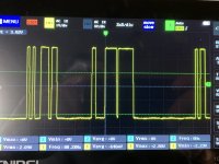
I was able to successfully obtain the i2s signal from JLSounds v3 on the AD1862 board and observe it on my scope at dl and dr points after passing it through shifts.
After reinstalling the DAC and OAMP chips, I played a 1kHz signal, but unfortunately, the graph on my scope appeared to be quite chaotic.
Instead of hearing the music, I noticed a distortion that sounded quite digital with sharp peaks. It's difficult for me to explain the distortion any better, but it's worth noting that when I stop the music source, the distortion also stops except for those sharp peaks.
I'm curious to know if anyone else in this thread has encountered similar symptoms. I wasn't able to find anything related to this issue other than THD-related discussions. Any insights or suggestions would be greatly appreciated.
Thank you!
@Vavilen It can be anything. People have often trouble with the SMD shift registers.
Since you have jlsounds v3, you can bypass these registers: cut the JP1 and JP2 and use pins DR and DL for connecting jlsounds directly.
Here is the connection diagram (jumper J4 is used and resistor 4k7, usb self-powered configuration) 😉
Since you have jlsounds v3, you can bypass these registers: cut the JP1 and JP2 and use pins DR and DL for connecting jlsounds directly.
Here is the connection diagram (jumper J4 is used and resistor 4k7, usb self-powered configuration) 😉
Attachments

Series R, I thinkPolymer caps are useful for local decoupling of DAC power supply pins though beware that if that cap's being fed by a 3pin regulator the low ESR of a polymer may well endanger its stability. If so, a series L would be called for.
The high leakage of polymers precludes their use for decoupling references, servos and BPO outputs of DAC chips.
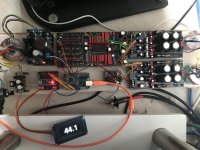
I finished my build of @miro1360 TDA1540 DAC yesterday and can confirm that she sings beautifully! 🙂 As with all Miro DACs the build was straightforward and the instructions on downloading needed software and programming the CPLD board worked first time - no issues. I ended up stacking and permanently wiring the PSU and DAC together as this will be my workshop DAC. My initial power on test was with LM6171 opamps, I later swapped them out for the Sparkos.
One thing I noticed is that if the CPLD board is not properly grounded it will introduce a lot of white noise alongside the audio, so if you encounter that, make sure everything is grounded together really well. For those that might feel a little intimidated by the CPLD approach, don't be! As long as you follow Miro's well written documentation you'll be fine.
Below are some pictures of the build hooked up to my test system showing the CPLD board feeding the DAC and another showing the DAC and PSU stacked.


A big thank you to Miro for all the hard work and freely sharing with this community!
One thing I noticed is that if the CPLD board is not properly grounded it will introduce a lot of white noise alongside the audio, so if you encounter that, make sure everything is grounded together really well. For those that might feel a little intimidated by the CPLD approach, don't be! As long as you follow Miro's well written documentation you'll be fine.
Below are some pictures of the build hooked up to my test system showing the CPLD board feeding the DAC and another showing the DAC and PSU stacked.
A big thank you to Miro for all the hard work and freely sharing with this community!
@psmith001 beautiful boards! I am still waiting for the delivery of my parts. I have done programming of the cpld board and yes, with Miro's tutorial, things are easy.👍
@psmith001 Nice build and thanks for your experience and confirmation of the working state 😊
I hope it serves you for a long time
I hope it serves you for a long time
I finished my build of @miro1360 TDA1540 DAC yesterday and can confirm that she sings beautifully! 🙂 As with all Miro DACs the build was straightforward and the instructions on downloading needed software and programming the CPLD board worked first time - no issues. I ended up stacking and permanently wiring the PSU and DAC together as this will be my workshop DAC. My initial power on test was with LM6171 opamps, I later swapped them out for the Sparkos.
One thing I noticed is that if the CPLD board is not properly grounded it will introduce a lot of white noise alongside the audio, so if you encounter that, make sure everything is grounded together really well. For those that might feel a little intimidated by the CPLD approach, don't be! As long as you follow Miro's well written documentation you'll be fine.
Below are some pictures of the build hooked up to my test system showing the CPLD board feeding the DAC and another showing the DAC and PSU stacked.
View attachment 1150104View attachment 1150105
A big thank you to Miro for all the hard work and freely sharing with this community!
Last edited:
Hi Abraxa!The high leakage of polymers precludes their use for decoupling references, servos and BPO outputs of DAC chips.
What is BPO outputs?
Thanx
Thorsten
Congratulations.Here is my TDA1541 DAC.

I see JLS I2S over USB, but also some display and display driver board. Can you tell me more about the display and the driver board?
- Home
- Source & Line
- Digital Line Level
- DAC AD1862: Almost THT, I2S input, NOS, R-2R