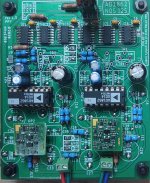
I just replaced the 797s with some Sparkos Labs discrete opamps and gave them a listen. Wow, a clear and easily perceptible improvement across the board, it really makes this DAC shine. The 797, and the other opamps I was planning to try are retired and not going back in. I am very impressed with this DAC, clearly bests all of my delta sigma DACs.
Attachments

https://www.diyaudio.com/community/...ke-ad797-like-lm741-did-you-buy-these.370952/ANZ. So I got 797sq yesterday. Planning to install a new Dac 1702 (if fix the problem)
They are from ali.
The photo I can made today late night.
Don't buy opamps from aliexpress 🤓
Enjoy the sound. It is delta-sigma killer 🤩I just replaced the 797s with some Sparkos Labs discrete opamps and gave them a listen. Wow, a clear and easily perceptible improvement across the board, it really makes this DAC shine. The 797, and the other opamps I was planning to try are retired and not going back in. I am very impressed with this DAC, clearly bests all of my delta sigma DACs.
🤓other opamps I was planning to try are retired and not going back in.
@sworder84 Add a note to your future review that opamps are not genuine 😊 Some untrusted sellers are remarking cheapest opamps for expensive brands and selling it 
Ok, I will know! I use the LM6171 from Mouser and I like them. Sparkos will be interesting but I didn't buy yet. Also I have OPA134 - not tested them. I guess they are more simple than 6171.@sworder84 Add a note to your future review that opamps are not genuine 😊 Some untrusted sellers are remarking cheapest opamps for expensive brands and selling it
Miro,SPDIF/Optical to I2S, almost THT, WM8804
Repaired (coupling capacitor in the SPDIF input is needed) ... otherwise it is the same as in the post #2139
Sorry for any inconvenience 😱
Components example, mouser:
IC1:238-WM8804GEDS
R7, R8, R9, R10:594-MBB02070C2209FCT
R4:594-MBB02070C7509FCT
R1, R3, R5, R6:594-MBB02070C1002FC1
JP1, JP2, X5:571-5-146284-2
JP3:571-5-146285-3
X4:571-5-146268-4
Q1:520-ECS120-18-4X-CKM
C13, C14:81-RCE5C2A180J0A2H3B
C16, C17:80-C324C104K1G5TA
C1, C3, C5, C7, C9, C10, C11:505-MKP2D031001FJO00
C12:505-MKS21.0/63/5
C15:667-EEU-FR1H100B
C2, C4, C6, C8:667-EEU-FR1E101
TR1:580-786013C
IC2, IC3:511-LF33ABV-DG
X1:651-1729128
X2:GP1FAV50RK0F Original and New SHARP Sensor | eBay
X3:502-PJRAN1X1U02AUX
(JP1, JP2, JP3):855-M7582-05
I tried out the spdif to i2s at post #2249 and with the exception of the errors already mentioned, the pcb worked beautifully. I however used a shunt regulator for the required 3v3 supply. I next intend to try out the new dac boards, but this time with the spdif pcb and with an option to use a usb to i2s/ usbto spdif card that are so easily available on ebay/ali express. At post #2909, you have a pcb design and gerbers for 3 input i2s switch. Although you have provided a design where there is incorporated a usb input using PCM2706, the newer xmos or amanero chipset ones provide greater functionality in that they can also do hi res 24 bit 192KHz or higher.
My request is whether you could incorporate both the spdif pcb designs with the 3 input i2s switch on one pcb and post the gerbers . It would really simply things a lot, without having to deal with too many separate pcb's. Thanks in advance.
Thanks for the extremely quick and prompt reply. I think it would be ideal if there were only one pcb for #2209 and #2249, with the necessary header input for an external usb to i2s input. This would enable different commercial usb to i2s boards to be incorporated, so as not to be limited to PCM2706.
Why not learn to use PCB software.
Then you can customise anything to your own needs.
Cheers,
Patrick
Then you can customise anything to your own needs.
Cheers,
Patrick
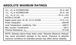
Is there an advantage to separating Vcc/Vdd in PCM63? Just to check.In one of the old datasheets TI goes so far as to recommend there is no advantage to using different supplies for Vcc/Vdd, and if you guys are coming from 12V/5V AD1862 circuits you may be using different supplies on the PCM1702 as well
There are guys on the board who have forgotten more about these parts than I’ll ever know, but given the architecture of the TI PCM DACs I would guess “no.”Is there an advantage to separating Vcc/Vdd in PCM63? Just to check.
Below are the data sheet max ratings, which you don’t want to violate on power-up, at a minimum.
The non-obvious mod to the 63 was IIRC a 2ma suck-out CCS on the BPO pin.
You can get D/S performance all day with op-amp or discrete circuits, pick your poison
Attachments
I have no idea. But I will hear soon 🤣Is there an advantage to separating Vcc/Vdd in PCM63? Just to check.
WM8804 is connected with input 1 or 2? 🙂Thanks for the extremely quick and prompt reply. I think it would be ideal if there were only one pcb for #2209 and #2249, with the necessary header input for an external usb to i2s input. This would enable different commercial usb to i2s boards to be incorporated, so as not to be limited to PCM2706.
Everyone has an opinion....so here is mine.
I reckon you are better off keeping the switch part as a single module, and spdif to i2s etc likewise. If a new source comes along eg Bluetooth, or even if you just want to test one against another, if you have them on headers you have more options.
There are of course advantages to putting them all on one board.
Does anybody know, can we use old version I2SOVERUSB product of JLSOUND with AD1955 and PCM1794A chipsets? If yes could you share connection info? I didn't get any answer from JLSOUND company.
Last edited:
http://jlsounds.com/i2soverusb_o.htmlDoes anybody know, can we use old version I2SOVERUSB product of JLSOUND with AD1955 and PCM1794A chipsets? If yes could you share connection info? I didn't get any answer from JLSOUND company.
Directly supports PCM1704, PCM63, PCM61, PCM58, PCM56, AD1862,
AD1865, AD1861, AD1860, AD1851 and other compatible with listed DACs
If AD1955 and PCM1794A can suppoart I2S than yes.
Hi,
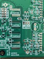
i just got some 1862/65 boards printed. However, I see that the Jp-1 and Jp-2 are already shorted.
Is this a QC issue from the factory; do I cut the traces before stuffing them? What options do they entail with/out the short
also, what are the x-1,2,3 socket mounted connectors called?
thanks in advanced
Attachments
How long can the i2s cables be? I was thinking of a 2 box solution, with the Toslink i2s in one box and the dac in another box, using with an xlr.Everyone has an opinion....so here is mine.
I reckon you are better off keeping the switch part as a single module, and spdif to i2s etc likewise. If a new source comes along eg Bluetooth, or even if you just want to test one against another, if you have them on headers you have more options.
There are of course advantages to putting them all on one board.
- Home
- Source & Line
- Digital Line Level
- DAC AD1862: Almost THT, I2S input, NOS, R-2R